Configuration example
Network requirements
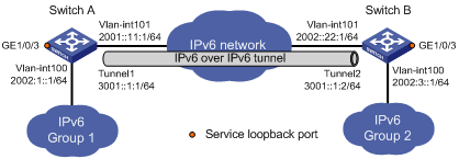
As shown in Figure 93, the two subnets Group 1 and Group 2 running IPv6 are connected through an IPv6 network. Configure an IPv6 over IPv6 tunnel between Switch A and Switch B to make the two subnets reachable to each other without disclosing their IPv6 addresses to the IPv6 network.
Figure 93: Network diagram
Configuration procedure
Before configuring an IPv6 over IPv6 tunnel, make sure Switch A and Switch B have the corresponding VLAN interfaces created and can reach each other.
Configure Switch A:
# Enable IPv6.
<SwitchA> system-view
[SwitchA] ipv6
# Specify an IPv6 address for VLAN-interface 100.
[SwitchA] interface vlan-interface 100
[SwitchA-Vlan-interface100] ipv6 address 2002:1::1 64
[SwitchA-Vlan-interface100] quit
# Specify an IPv6 address for VLAN-interface 101, the physical interface of the tunnel.
[SwitchA] interface vlan-interface 101
[SwitchA-Vlan-interface101] ipv6 address 2001::11:1 64
[SwitchA-Vlan-interface101] quit
# Create service loopback group 1 to support the tunnel service.
[SwitchA] service-loopback group 1 type tunnel
# Assign GigabitEthernet 1/0/3 to service loopback group 1, and disable STP, NDP, and LLDP on the interface.
[SwitchA] interface GigabitEthernet 1/0/3
[SwitchA-GigabitEthernet1/0/3] undo stp enable
[SwitchA-GigabitEthernet1/0/3] undo ndp enable
[SwitchA-GigabitEthernet1/0/3] undo lldp enable
[SwitchA-GigabitEthernet1/0/3] port service-loopback group 1
[SwitchA-GigabitEthernet1/0/3] quit
# Create interface Tunnel 1.
[SwitchA] interface tunnel 1
# Specify an IPv6 address for interface Tunnel 1.
[SwitchA-Tunnel1] ipv6 address 3001::1:1 64
# Configure the tunnel encapsulation mode.
[SwitchA-Tunnel1] tunnel-protocol ipv6-ipv6
# Specify the IP address of VLAN-interface 101 as the source address for interface Tunnel 1.
[SwitchA-Tunnel1] source 2001::11:1
# Specify the IP address of VLAN-interface 101 on Switch B as the destination address for interface Tunnel 1.
[SwitchA-Tunnel1] destination 2002::22:1
# Reference service loopback group 1 on the tunnel.
[SwitchA-Tunnel1] service-loopback-group 1
[SwitchA-Tunnel1] quit
# Configure a static route from Switch A through interface Tunnel 1 to Group 2.
[SwitchA] ipv6 route-static 2002:3:: 64 tunnel 1
Configure Switch B:
# Enable IPv6.
<SwitchB> system-view
[SwitchB] ipv6
# Specify an IPv6 address for VLAN-interface 100.
[SwitchB] interface vlan-interface 100
[SwitchB-Vlan-interface100] ipv6 address 2002:3::1 64
[SwitchB-Vlan-interface100] quit
# Specify an IPv6 address for VLAN-interface 101, the physical interface of the tunnel.
[SwitchB] interface vlan-interface 101
[SwitchB-Vlan-interface101] ipv6 address 2002::22:1 64
[SwitchB-Vlan-interface101] quit
# Create service loopback group 1 to support the tunnel service.
[SwitchB] service-loopback group 1 type tunnel
# Assign GigabitEthernet 1/0/3 to service loopback group 1, and disable STP, NDP, and LLDP on the interface.
[SwitchB] interface GigabitEthernet 1/0/3
[SwitchB-GigabitEthernet1/0/3] undo stp enable
[SwitchB-GigabitEthernet1/0/3] undo ndp enable
[SwitchB-GigabitEthernet1/0/3] undo lldp enable
[SwitchB-GigabitEthernet1/0/3] port service-loopback group 1
[SwitchB-GigabitEthernet1/0/3] quit
# Create interface Tunnel 2.
[SwitchB] interface tunnel 2
# Specify an IPv6 address for interface Tunnel 2.
[SwitchB-Tunnel2] ipv6 address 3001::1:2 64
# Configure the tunnel encapsulation mode.
[SwitchB-Tunnel2] tunnel-protocol ipv6-ipv6
# Specify the IP address of VLAN-interface 101 as the source address for interface Tunnel 2.
[SwitchB-Tunnel2] source 2002::22:1
# Specify the IP address of VLAN-interface 101 on Switch A as the destination address for interface Tunnel 2.
[SwitchB-Tunnel2] destination 2001::11:1
# Reference service loopback group 1 on the tunnel.
[SwitchB-Tunnel2] service-loopback-group 1
[SwitchB-Tunnel2] quit
# Configure a static route from Switch B through interface Tunnel 2 to Group 1.
[SwitchB] ipv6 route-static 2002:1:: 64 tunnel 2
Verifying the configuration
Display the status of the tunnel interfaces on Switch A and Switch B.
[SwitchA] display ipv6 interface tunnel 1
Tunnel1 current state :UP
Line protocol current state :UP
IPv6 is enabled, link-local address is FE80::2013:1
  Global unicast address(es):
    3001::1:1, subnet is 3001::/64
  Joined group address(es):
    FF02::1:FF13:1
    FF02::1:FF01:1
    FF02::1:FF00:0
    FF02::2
    FF02::1
  MTU is 1460 bytes
  ND reachable time is 30000 milliseconds
  ND retransmit interval is 1000 milliseconds
  Hosts use stateless autoconfig for addresses
IPv6 Packet statistics:
...
[SwitchB] display ipv6 interface tunnel 2
Tunnel2 current state :UP
Line protocol current state :UP
IPv6 is enabled, link-local address is FE80::2024:1
  Global unicast address(es):
    3001::1:2, subnet is 3001::/64
  Joined group address(es):
    FF02::1:FF24:1
    FF02::1:FF01:2
    FF02::1:FF00:0
    FF02::2
    FF02::1
  MTU is 1460 bytes
  ND reachable time is 30000 milliseconds
  ND retransmit interval is 1000 milliseconds
  Hosts use stateless autoconfig for addresses
IPv6 Packet statistics:
...
# Ping the IPv6 address of the peer interface VLAN-interface 100 from Switch A.
[SwitchA] ping ipv6 2002:3::1
  PING 2002:3::1 : 56  data bytes, press CTRL_C to break
    Reply from 2002:3::1
    bytes=56 Sequence=1 hop limit=64  time = 31 ms
    Reply from 2002:3::1
    bytes=56 Sequence=2 hop limit=64  time = 1 ms
    Reply from 2002:3::1
    bytes=56 Sequence=3 hop limit=64  time = 16 ms
    Reply from 2002:3::1
    bytes=56 Sequence=4 hop limit=64  time = 16 ms
    Reply from 2002:3::1
    bytes=56 Sequence=5 hop limit=64  time = 31 ms

  --- 2002:3::1 ping statistics ---
    5 packet(s) transmitted
    5 packet(s) received
    0.00% packet loss
    round-trip min/avg/max = 1/19/31 ms