Network requirements
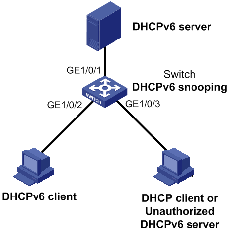
As shown in Figure 75, Switch is connected to a DHCPv6 server through GigabitEthernet 1/0/1, and is connected to DHCPv6 clients through GigabitEthernet 1/0/2 and GigabitEthernet 1/0/3. These three interfaces belong to VLAN 2. Configure Switch to forward DHCPv6 reply messages received on GigabitEthernet 1/0/1 only and record the IP-to-MAC mappings for DHCPv6 clients.
Figure 75: Network diagram