Network requirements
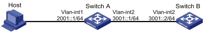
As shown in Figure 59, a host, Switch A and Switch B are connected through Ethernet ports. Add the Ethernet ports into corresponding VLANs, configure IPv6 addresses for the VLAN interfaces and verify that they are connected.
The global unicast addresses of VLAN-interface 1 and VLAN-interface 2 on Switch A are 2001::1/64 and 3001::1/64, respectively.
The global unicast address of VLAN-interface 2 on Switch B is 3001::2/64, and a route to Host is available.
IPv6 is enabled for the host to automatically obtain an IPv6 address through IPv6 ND, and a route to Switch B is available.
Figure 59: Network diagram
The VLAN interfaces have been created on the switch.