Network requirements
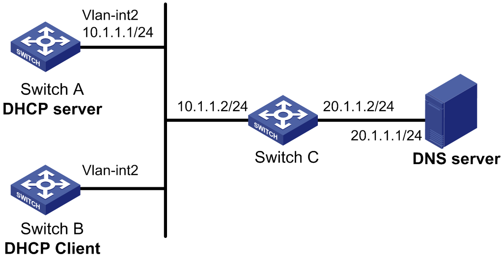
As shown in Figure 35, on a LAN, Switch B contacts the DHCP server via VLAN-interface 2 to obtain an IP address, DNS server address, and static route information. The DHCP client IP address resides on network 10.1.1.0/24. The DNS server address is 20.1.1.1. The next hop of the static route to network 20.1.1.0/24 is 10.1.1.2.
The DHCP server uses Option 121 to assign static route information to DHCP clients. The destination descriptor field comprises two parts, subnet mask length and destination network address. In this example, the value of the destination descriptor field takes 18 14 01 01, a hexadecimal number indicating that the subnet mask length is 24 and destination network address is 20.1.1.0. The value of the next hop address field takes 0A 01 01 02, a hexadecimal number indicating that the next hop is 10.1.1.2.
Figure 35: Network diagram