Local proxy ARP configuration example in case of port isolation
Network requirements
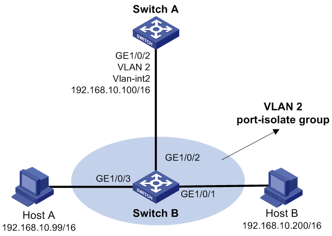
As shown in Figure 9, Host A and Host B belong to the same VLAN, and connect to Switch B via GigabitEthernet 1/0/3 and GigabitEthernet 1/0/1 respectively. Switch B connects to Switch A via GigabitEthernet 1/0/2.
Configure port isolation on GigabitEthernet 1/0/3 and GigabitEthernet 1/0/1 of Switch B to isolate Host A from Host B at Layer 2. Enable local proxy ARP on Switch A to allow communication between Host A and Host B at Layer 3.
Figure 9: Network diagram
Configuration procedure
Configure Switch B:
# Add GigabitEthernet 1/0/3, GigabitEthernet 1/0/1 and GigabitEthernet 1/0/2 to VLAN 2. Configure port isolation on Host A and Host B.
<SwitchB> system-view
[SwitchB] vlan 2
[SwitchB-vlan2] port GigabitEthernet 1/0/3
[SwitchB-vlan2] port GigabitEthernet 1/0/1
[SwitchB-vlan2] port GigabitEthernet 1/0/2
[SwitchB-vlan2] quit
[SwitchB] interface GigabitEthernet 1/0/3
[SwitchB-GigabitEthernet1/0/3] port-isolate enable
[SwitchB-GigabitEthernet1/0/3] quit
[SwitchB] interface GigabitEthernet 1/0/1
[SwitchB-GigabitEthernet1/0/1] port-isolate enable
[SwitchB-GigabitEthernet1/0/1] quit
Configure Switch A:
# Create VLAN 2, and add GigabitEthernet 1/0/2 to VLAN 2.
<SwitchA> system-view
[SwitchA] vlan 2
[SwitchA-vlan2] port GigabitEthernet 1/0/2
[SwitchA-vlan2] quit
[SwitchA] interface vlan-interface 2
[SwitchA-Vlan-interface2] ip address 192.168.10.100 255.255.0.0
From Host A, ping Host B. The ping operation is unsuccessful because they are isolated at Layer 2.
# Configure local proxy ARP to allow communication between Host A and Host B at Layer 3.
[SwitchA-Vlan-interface2] local-proxy-arp enable
From Host A, ping Host B. The ping operation is successful after the configuration.