Multicast VLAN configuration examples
Network requirements
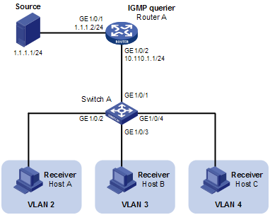
As shown in Figure 19, Router A connects to a multicast source—Source—through GigabitEthernet1/0/1, and to Switch A through GigabitEthernet1/0/2.
IGMPv2 is required on Router A. IGMPv2 snooping is required on Switch A. Router A acts as the IGMP querier.
Switch A's GigabitEthernet1/0/1 belongs to VLAN 10, GigabitEthernet1/0/2 through GigabitEthernet1/0/4 belong to VLAN 2 through VLAN 4 respectively, and Host A through Host C are attached to GigabitEthernet1/0/2 through GigabitEthernet1/0/4 of Switch A respectively.
The multicast source sends multicast data to multicast group 224.1.1.1. Host A, Host B, and Host C are receivers of the multicast group.
Configure the port-based multicast VLAN feature so that Router A just sends multicast data to Switch A through the multicast VLAN and Switch A forwards the multicast data to the receivers that belong to different user VLANs.
Network diagram
Figure 19: Network diagram for port-based multicast VLAN configuration
Configuration procedure
Configure IP addresses
Configure the IP address and subnet mask for each interface according to Figure 19. The detailed configuration steps are omitted here.
Configure Router A
# Enable IP multicast routing, enable PIM-DM on each interface, and enable IGMP on the host-side interface GigabitEthernet1/0/2.
<RouterA> system-view
[RouterA] multicast routing-enable
[RouterA] interface gigabitethernet 1/0/1
[RouterA-GigabitEthernet1/0/1] pim dm
[RouterA-GigabitEthernet1/0/1] quit
[RouterA] interface gigabitethernet 1/0/2
[RouterA-GigabitEthernet1/0/2] pim dm
[RouterA-GigabitEthernet1/0/2] igmp enable
Configure Switch A
# Enable IGMP snooping globally.
<SwitchA> system-view
[SwitchA] igmp-snooping
[SwitchA-igmp-snooping] quit
# Create VLAN 10, assign GigabitEthernet1/0/1 to VLAN 10, and enable IGMP snooping in this VLAN.
[SwitchA] vlan 10
[SwitchA-vlan10] port gigabitethernet 1/0/1
[SwitchA-vlan10] igmp-snooping enable
[SwitchA-vlan10] quit
# Create VLAN 2 and enable IGMP snooping in the VLAN.
[SwitchA] vlan 2
[SwitchA-vlan2] igmp-snooping enable
[SwitchA-vlan2] quit
The configuration for VLAN 3 and VLAN 4 is similar. The detailed configuration steps are omitted.
# Configure GigabitEthernet1/0/2 as a hybrid port. Configure VLAN 2 as the default VLAN. Configure GigabitEthernet1/0/2 to permit packets of VLAN 2 and VLAN 10 to pass and untag the packets when forwarding them.
[SwitchA] interface gigabitethernet 1/0/2
[SwitchA-GigabitEthernet1/0/2] port link-type hybrid
[SwitchA-GigabitEthernet1/0/2] port hybrid pvid vlan 2
[SwitchA-GigabitEthernet1/0/2] port hybrid vlan 2 untagged
[SwitchA-GigabitEthernet1/0/2] port hybrid vlan 10 untagged
[SwitchA-GigabitEthernet1/0/2] quit
The configuration for GigabitEthernet1/0/3 and GigabitEthernet1/0/4 is similar. The detailed configuration steps are omitted.
# Configure VLAN 10 as a multicast VLAN.
[SwitchA] multicast-vlan 10
# Assign GigabitEthernet1/0/2 and GigabitEthernet1/0/3 to VLAN 10.
[SwitchA-mvlan-10] port gigabitethernet 1/0/2 to gigabitethernet 1/0/3
[SwitchA-mvlan-10] quit
# Assign GigabitEthernet1/0/4 to VLAN 10.
[SwitchA] interface gigabitethernet 1/0/4
[SwitchA-GigabitEthernet1/0/4] port multicast-vlan 10
[SwitchA-GigabitEthernet1/0/4] quit
Verify the configuration
# View the multicast VLAN information on Switch A.
[SwitchA] display multicast-vlan
 Total 1 multicast-vlan(s)

 Multicast vlan 10
    port list:
    GE1/0/2                 GE1/0/3                 GE1/0/4
# View the IGMP snooping multicast group information on Switch A.
[SwitchA] display igmp-snooping group
  Total 1 IP Group(s).
  Total 1 IP Source(s).
  Total 1 MAC Group(s).

  Port flags: D-Dynamic port, S-Static port, C-Copy port
  Subvlan flags: R-Real VLAN, C-Copy VLAN
  Vlan(id):10.
    Total 1 IP Group(s).
    Total 1 IP Source(s).
    Total 1 MAC Group(s).
    Router port(s):total 1 port(s).
            GE1/0/1                (D)
    IP group(s):the following ip group(s) match to one mac group.
      IP group address:224.1.1.1
        (0.0.0.0, 224.1.1.1):
          Host port(s):total 3 port(s).
            GE1/0/2                (D)
            GE1/0/3                (D)
            GE1/0/4                (D)
    MAC group(s):
      MAC group address:0100-5e01-0101
          Host port(s):total 3 port(s).
            GE1/0/2
            GE1/0/3
            GE1/0/4
The output shows that IGMP snooping is maintaining the router ports and member ports in VLAN 10.