Introduction to multicast VLAN
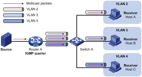
In the traditional multicast programs-on-demand mode shown in Figure 17, when hosts (Host A, Host B and Host C) that belong to different VLANs require multicast programs on demand service, the Layer 3 device (Router A) must forward a separate copy of the multicast traffic in each user VLAN to the Layer 2 device (Switch A). This results in not only waste of network bandwidth but also extra burden on the Layer 3 device.
Figure 17: Multicast transmission without multicast VLAN
The multicast VLAN feature configured on the Layer 2 switch is the solution to this issue. With the multicast VLAN feature, the Layer 3 device must replicate the multicast traffic only in the multicast VLAN instead of making a separate copy of the multicast traffic in each user VLAN. This saves network bandwidth and lessens the burden on the Layer 3 device.
As shown in Figure 18, Host A, Host B and Host C are in three different user VLANs. All user ports—ports with attached hosts—on Switch A are hybrid ports. On Switch A, configure VLAN 10 as a multicast VLAN, assign all user ports to this multicast VLAN, and enable IGMP snooping in the multicast VLAN and all user VLANs.
Figure 18: Port-based multicast VLAN
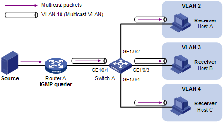
After the configuration, upon receiving an IGMP message on a user port, Switch A tags the message with the multicast VLAN ID and relays it to the IGMP querier, so that IGMP snooping can uniformly manage the router ports and member ports in the multicast VLAN. When forwarding multicast data to Switch A, Router A needs to send only one copy of multicast traffic to Switch A in the multicast VLAN, and Switch A distributes the traffic to all member ports in the multicast VLAN.
![[NOTE: ]](images/note.png) | NOTE: For more information about IGMP snooping, router ports, and member ports, see the chapter "IGMP snooping configuration." For more information about VLAN tags, see the Layer 2—LAN Switching Configuration Guide. | |