Area based OSPF network partition
Network partition
In a large OSPF routing domain, the LSDB becomes very huge and SPF computation consumes many storage and CPU resources.
In addition, because topology changes can easily occur, OSPF packets generated for route information synchronization are enormous, occupying excessive bandwidth.
To solve these problems, OSPF splits an AS into multiple areas, each of which is identified by an area ID. The boundaries between areas are routers rather than links. A network segment (or a link) can only reside in one area. An OSPF interface must be specified to belong to its attached area, as shown in Figure 17.
Figure 17: Area based OSPF network partition
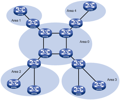
After network partition, ABRs perform route summarization to reduce the number of LSAs advertised to other areas and minimize the effect of topology changes.
Backbone area and virtual links
Each AS has a backbone area that distributes routing information between none-backbone areas. Routing information between non-backbone areas must be forwarded by the backbone area. OSPF requires the following:
All non-backbone areas must maintain connectivity to the backbone area.
The backbone area itself must maintain connectivity.
In practice, the requirements may not be satisfied due to lack of physical links. OSPF virtual links can solve this problem.
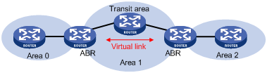
A virtual link is established between two ABRs through a non-backbone area and is configured on both ABRs to take effect. The non-backbone area is called a transit area.
In the following figure, Area 2 has no direct physical link to the backbone area 0. You can configure a virtual link between the two ABRs to connect Area 2 to the backbone area.
Figure 18: Virtual link application 1
Virtual links can also be used to provide redundant links. If the backbone area cannot maintain internal connectivity due to the failure of a physical link, you can configure a virtual link to replace the failed physical link, as shown in Figure 19.
Figure 19: Virtual link application 2

The virtual link between the two ABRs acts as a point-to-point connection. You can configure interface parameters such as hello interval on the virtual link as they are configured on a physical interface.
The two ABRs on the virtual link unicast OSPF packets to each other, and the OSPF routers in between convey these OSPF packets as normal IP packets.
Stub area
A stub area does not distribute Type-5 LSAs, so the routing table size and amount of routing information in this area are reduced significantly. The ABR generates a default route into the area.
You can configure the stub area as a totally stub area, where the ABR advertises neither inter-area routes nor external routes.
Stub area configuration is optional, and not every area is eligible to be a stub area. In general, a stub area resides on the border of the AS.
When you configure a totally stub area, follow these guidelines:
The backbone area cannot be a totally stub area.
To configure an area as a stub area, the stub command must be configured on routers in the area.
To configure an area as a totally stub area, the stub command must be configured on routers in the area, and the ABR of the area must be configured with the stub [ no-summary ] command.
A totally stub area cannot have an ASBR because AS external routes cannot be distributed into the stub area.
Virtual links cannot transit totally stub areas.
NSSA area
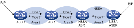
Similar to a stub area, an NSSA area does not import AS external LSAs (Type-5 LSAs), but can import Type-7 LSAs generated by the NSSA ASBR. The NSSA ABR translates Type-7 LSAs into Type-5 LSAs and advertises the Type-5 LSAs to other areas.
In the following figure, the OSPF AS contains Area 1, Area 2, and Area 0. The other two ASs run RIP. Area 1 is an NSSA area. The ASBR redistributes RIP routes in Type-7 LSAs into Area 1. Upon receiving these Type-7 LSAs, the NSSA ABR translates them to Type-5 LSAs, and then advertises the Type-5 LSAs to Area 0.
The ASBR of Area 2 redistributes RIP routes in Type-5 LSAs into the OSPF routing domain. However, Area 1 does not receive these Type-5 LSAs because it is an NSSA area.
Virtual links cannot transit NSSA areas.
Figure 20: NSSA area
Comparison between the areas
Figure 21: Comparison between the areas

Figure 21 shows the comparison of the areas:
In a totally stub area, the ABR distributes a Type 3 default route, rather than external routes and inter-area routes.
A stub area can import inter-area routes, but a stub area cannot.
An NSSA area can import external routes in Type 7 LSAs through the ASBR, but a stub area cannot.
A totally NSSA area cannot import inter-area routes but an NSSA area can.