Configuring the MCE that uses OSPF to advertise VPN routes to the PE
Network requirements
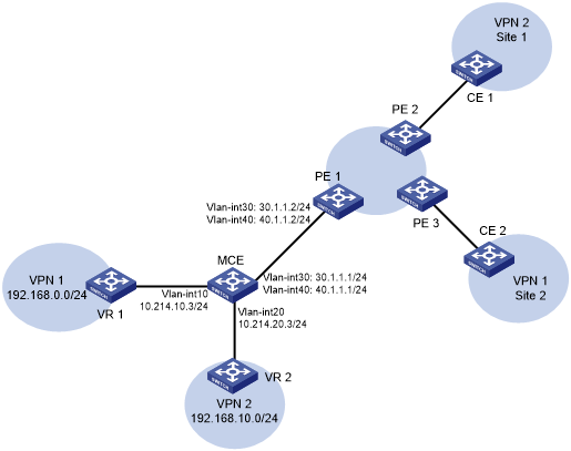
As shown in Figure 79, VPN 2 runs OSPF. Configure the MCE device to separate routes from different VPNs and to advertise the VPN routes to PE 1 through OSPF.
Figure 79: Network diagram
Configuration procedure
Assume that the system name of the MCE device is MCE, the system names of the edge devices of VPN 1 and VPN 2 are VR 1 and VR 2, respectively, and the system name of PE 1 is PE1.
Configure the VPN instances on the MCE and PE 1:
# On the MCE, configure VPN instances vpn1 and vpn2, and specify an RD and route targets for each VPN instance.
<MCE> system-view
[MCE] ip vpn-instance vpn1
[MCE-vpn-instance-vpn1] route-distinguisher 10:1
[MCE-vpn-instance-vpn1] vpn-target 10:1
[MCE-vpn-instance-vpn1] quit
[MCE] ip vpn-instance vpn2
[MCE-vpn-instance-vpn2] route-distinguisher 20:1
[MCE-vpn-instance-vpn2] vpn-target 20:1
[MCE-vpn-instance-vpn2] quit
# Bind VLAN-interface 10 to VPN instance vpn1, and configure an IP address for the VLAN interface.
[MCE] interface vlan-interface 10
[MCE-Vlan-interface10] ip binding vpn-instance vpn1
[MCE-Vlan-interface10] ip address 10.214.10.3 24
[MCE-Vlan-interface10] quit
# Bind VLAN-interface 20 to VPN instance vpn2, and configure an IP address for the VLAN interface.
[MCE] interface vlan-interface 20
[MCE-Vlan-interface20] ip binding vpn-instance vpn2
[MCE-Vlan-interface20] ip address 10.214.20.3 24
[MCE-Vlan-interface20] quit
# On PE 1, configure VPN instances vpn1 and vpn2, and specify an RD and route targets for each VPN instance.
<PE1> system-view
[PE1] ip vpn-instance vpn1
[PE1-vpn-instance-vpn1] route-distinguisher 10:1
[PE1-vpn-instance-vpn1] vpn-target 10:1
[PE1-vpn-instance-vpn1] quit
[PE1] ip vpn-instance vpn2
[PE1-vpn-instance-vpn2] route-distinguisher 20:1
[PE1-vpn-instance-vpn2] vpn-target 20:1
[PE1-vpn-instance-vpn2] quit
Configure routing between the MCE and VPN sites:
The MCE is connected to VPN 1 directly, and no routing protocol is enabled in VPN 1. Therefore, you can configure static routes.
# On VR 1, assign IP address 10.214.10.2/24 to the interface connected to MCE and 192.168.0.1/24 to the interface connected to VPN 1. Add ports to VLANs correctly. (Details not shown.)
# On VR 1, configure a default route with the next hop being 10.214.10.3.
<VR1> system-view
[VR1] ip route-static 0.0.0.0 0.0.0.0 10.214.10.3
# On the MCE, configure a static route to 192.168.0.0/24 with the next hop 10.214.10.2. Bind the static route to VPN instance vpn1.
[MCE] ip route-static vpn-instance vpn1 192.168.0.0 24 10.214.10.2
# On the MCE, display the routing information maintained for VPN instance vpn1.
[MCE] display ip routing-table vpn-instance vpn1

Destinations : 13        Routes : 13

Destination/Mask   Proto   Pre Cost        NextHop         Interface
0.0.0.0/32         Direct  0   0           127.0.0.1       InLoop0
10.214.10.0/24     Direct  0   0           10.214.10.3     Vlan10
10.214.10.0/32     Direct  0   0           10.214.10.3     Vlan10
10.214.10.3/32     Direct  0   0           127.0.0.1       InLoop0
10.214.10.255/32   Direct  0   0           10.214.10.3     Vlan10
127.0.0.0/8        Direct  0   0           127.0.0.1       InLoop0
127.0.0.0/32       Direct  0   0           127.0.0.1       InLoop0
127.0.0.1/32       Direct  0   0           127.0.0.1       InLoop0
127.255.255.255/32 Direct  0   0           127.0.0.1       InLoop0
192.168.0.0/24     Static  60  0           10.214.10.2     Vlan10
224.0.0.0/4        Direct  0   0           0.0.0.0         NULL0
224.0.0.0/24       Direct  0   0           0.0.0.0         NULL0
255.255.255.255/32 Direct  0   0           127.0.0.1       InLoop0
The output shows that the MCE has a static route for VPN instance vpn1.
# Run OSPF in VPN 2. Create OSPF process 20 and bind it to VPN instance vpn2 on the MCE, so that the MCE can learn the routes of VPN 2 and add them to the routing table of VPN instance vpn2.
[MCE] ospf 2 vpn-instance vpn2
# Advertise subnet 10.214.20.0.
[MCE-ospf-2] area 0
[MCE-ospf-2-area-0.0.0.0] network 10.214.20.0 0.0.0.255
[MCE-ospf-2-area-0.0.0.0] quit
[MCE-ospf-2] quit
# On VR 2, assign IP address 10.214.20.2/24 to the interface connected to MCE and 192.168.10.1/24 to the interface connected to VPN 2. (Details not shown.)
# Configure OSPF process 2, and advertise subnets 192.168.10.0 and 10.214.20.0.
<VR2> system-view
[VR2] ospf 2
[VR2-ospf-2] area 0
[VR2-ospf-2-area-0.0.0.0] network 192.168.10.0 0.0.0.255
[VR2-ospf-2-area-0.0.0.0] network 10.214.20.0 0.0.0.255
[VR2-ospf-2-area-0.0.0.0] quit
[VR2-ospf-2] quit
# On the MCE, display the routing information maintained for VPN instance vpn2.
[MCE] display ip routing-table vpn-instance vpn2

Destinations : 13        Routes : 13

Destination/Mask   Proto   Pre Cost        NextHop         Interface
0.0.0.0/32         Direct  0   0           127.0.0.1       InLoop0
10.214.20.0/24     Direct  0   0           10.214.20.3     Vlan20
10.214.20.0/32     Direct  0   0           10.214.20.3     Vlan20
10.214.20.3/32     Direct  0   0           127.0.0.1       InLoop0
10.214.20.255/32   Direct  0   0           10.214.20.3     Vlan20
127.0.0.0/8        Direct  0   0           127.0.0.1       InLoop0
127.0.0.0/32       Direct  0   0           127.0.0.1       InLoop0
127.0.0.1/32       Direct  0   0           127.0.0.1       InLoop0
127.255.255.255/32 Direct  0   0           127.0.0.1       InLoop0
192.168.10.0/24    O_INTRA 10  2           10.214.20.2     Vlan20
224.0.0.0/4        Direct  0   0           0.0.0.0         NULL0
224.0.0.0/24       Direct  0   0           0.0.0.0         NULL0
255.255.255.255/32 Direct  0   0           127.0.0.1       InLoop0
The output shows that the MCE has learned the private routes of VPN 2. The MCE maintains the routes of VPN 1 and those of VPN2 in two different routing tables. In this way, routes from different VPNs are separated.
Configure routing between the MCE and PE 1:
# On the MCE, bind VLAN-interface 30 to VPN instance vpn1, and configure an IP address for the VLAN interface.
[MCE] interface vlan-interface 30
[MCE-Vlan-interface30] ip binding vpn-instance vpn1
[MCE-Vlan-interface30] ip address 30.1.1.1 24
[MCE-Vlan-interface30] quit
# Bind VLAN-interface 40 to VPN instance vpn2, and configure an IP address for the VLAN interface.
[MCE] interface vlan-interface 40
[MCE-Vlan-interface40] ip binding vpn-instance vpn2
[MCE-Vlan-interface40] ip address 40.1.1.1 24
[MCE-Vlan-interface40] quit
# On PE 1, bind VLAN-interface 30 to VPN instance vpn1, and configure an IP address for the VLAN interface.
[PE1] interface vlan-interface 30
[PE1-Vlan-interface30] ip binding vpn-instance vpn1
[PE1-Vlan-interface30] ip address 30.1.1.2 24
[PE1-Vlan-interface30] quit
# Bind VLAN-interface 40 to VPN instance vpn2, and configure an IP address for the VLAN interface.
[PE1] interface vlan-interface 40
[PE1-Vlan-interface40] ip binding vpn-instance vpn2
[PE1-Vlan-interface40] ip address 40.1.1.2 24
[PE1-Vlan-interface40] quit
# Configure the IP address of the interface Loopback 0 as 101.101.10.1 for the MCE and as 100.100.10.1 for PE 1. Specify the loopback interface address as the router ID for the MCE and PE 1. (Details not shown.)
# Enable OSPF process 10 on the MCE, and bind the process to VPN instance vpn1.
[MCE] ospf 10 router-id 101.101.10.1 vpn-instance vpn1
# Disable OSPF routing loop detection for the VPN instance.
[MCE-ospf-10] vpn-instance-capability simple
# Set the domain ID to 10.
[MCE-ospf-10] domain-id 10
# On the MCE, advertise subnet 30.1.1.0 in area 0, and redistribute the static route of VPN 1.
[MCE-ospf-10] area 0
[MCE-ospf-10-area-0.0.0.0] network 30.1.1.0 0.0.0.255
[MCE-ospf-10-area-0.0.0.0] quit
[MCE-ospf-10] import-route static
# On PE 1, enable OSPF process 10, and bind the process to VPN instance vpn1.
[PE1] ospf 10 router-id 100.100.10.1 vpn-instance vpn1
# Set the domain ID to 10.
[PE1-ospf-10] domain-id 10
# Advertise subnet 30.1.1.0 in area 0.
[PE1-ospf-10] area 0
[PE1-ospf-10-area-0.0.0.0] network 30.1.1.0 0.0.0.255
[PE1-ospf-10-area-0.0.0.0] quit
[PE1-ospf-10] quit
# Use similar procedures to configure OSPF process 2 between MCE and PE 1 and redistribute VPN 2's routing information. (Details not shown.)
Verifying the configuration
# Verify that PE 1 has learned the static route of VPN 1 through OSPF.
[PE1] display ip routing-table vpn-instance vpn1

Destinations : 13        Routes : 13

Destination/Mask   Proto   Pre Cost        NextHop         Interface
0.0.0.0/32         Direct  0   0           127.0.0.1       InLoop0
30.1.1.0/24        Direct  0   0           30.1.1.2        Vlan30
30.1.1.0/32        Direct  0   0           30.1.1.2        Vlan30
30.1.1.2/32        Direct  0   0           127.0.0.1       InLoop0
30.1.1.255/32      Direct  0   0           30.1.1.2        Vlan30
127.0.0.0/8        Direct  0   0           127.0.0.1       InLoop0
127.0.0.0/32       Direct  0   0           127.0.0.1       InLoop0
127.0.0.1/32       Direct  0   0           127.0.0.1       InLoop0
127.255.255.255/32 Direct  0   0           127.0.0.1       InLoop0
192.168.0.0/24     O_ASE2  150 1           30.1.1.1        Vlan30
224.0.0.0/4        Direct  0   0           0.0.0.0         NULL0
224.0.0.0/24       Direct  0   0           0.0.0.0         NULL0
255.255.255.255/32 Direct  0   0           127.0.0.1       InLoop0
# Verify that PE 1 has learned the routes of OSPF process 2 in VPN 2 through OSPF.
[PE1] display ip routing-table vpn-instance vpn2

Destinations : 13        Routes : 13

Destination/Mask   Proto   Pre Cost        NextHop         Interface
0.0.0.0/32         Direct  0   0           127.0.0.1       InLoop0
40.1.1.0/24        Direct  0   0           40.1.1.2        Vlan40
40.1.1.0/32        Direct  0   0           40.1.1.2        Vlan40
40.1.1.2/32        Direct  0   0           127.0.0.1       InLoop0
40.1.1.255/32      Direct  0   0           40.1.1.2        Vlan40
127.0.0.0/8        Direct  0   0           127.0.0.1       InLoop0
127.0.0.0/32       Direct  0   0           127.0.0.1       InLoop0
127.0.0.1/32       Direct  0   0           127.0.0.1       InLoop0
127.255.255.255/32 Direct  0   0           127.0.0.1       InLoop0
192.168.10.0/24    O_ASE2  150 1           40.1.1.1        Vlan40
224.0.0.0/4        Direct  0   0           0.0.0.0         NULL0
224.0.0.0/24       Direct  0   0           0.0.0.0         NULL0
255.255.255.255/32 Direct  0   0           127.0.0.1       InLoop0
The routing information for the two VPNs has been redistributed into the routing tables on PE 1.