Configuring BGP AS number substitution and SoO attribute
Network requirements
CE 1, CE 2, and CE 3 belong to VPN 1, and are connected to PE1, PE 2, and PE 3, respectively.
CE 1 and CE 2 reside in the same site. CE1, CE2, and CE 3 all use AS number 600.
To avoid route loss, configure BGP AS number substitution on PEs.
To avoid routing loops, configure the same SoO attribute on PE 1 and PE 2 for CE 1 and CE 2.
Figure 74: Network diagram
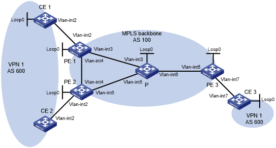
Table 23: Interface and IP address assignment
Device | Interface | IP address | Device | Interface | IP address |
|---|---|---|---|---|---|
CE 1 | Loop0 | 100.1.1.1/32 | CE 3 | Loop0 | 200.1.1.1/32 |
Vlan-int2 | 10.1.1.1/24 | Vlan-int7 | 10.3.1.1/24 | ||
CE 2 | Vlan-int2 | 10.2.1.1/24 | PE 2 | Loop0 | 2.2.2.9/32 |
PE 1 | Loop0 | 1.1.1.9/32 | Vlan-int2 | 10.2.1.2/24 | |
Vlan-int2 | 10.1.1.2/24 | Vlan-int4 | 40.1.1.2/24 | ||
Vlan-int3 | 30.1.1.1/24 | Vlan-int5 | 50.1.1.1/24 | ||
Vlan-int4 | 40.1.1.1/24 | P | Loop0 | 3.3.3.9/32 | |
PE 3 | Loop0 | 4.4.4.9/32 | Vlan-int3 | 30.1.1.2/24 | |
Vlan-int6 | 60.1.1.2/24 | Vlan-int5 | 50.1.1.2/24 | ||
Vlan-int7 | 10.3.1.2/24 | Vlan-int6 | 60.1.1.1/24 |
Configuration procedure
Configure basic MPLS L3VPN:
Configure OSPF on the MPLS backbone to allow the PEs and P device to learn the routes of the loopback interfaces from each other.
Configure basic MPLS and MPLS LDP on the MPLS backbone to establish LDP LSPs.
Establish an MP-IBGP peer relationship between the PEs to advertise VPN IPv4 routes.
Configure the VPN instance of VPN 1 on PE 1 to allow CE 1 to access the network.
Configure the VPN instance of VPN 1 on PE 2 to allow CE 2 to access the network.
Configure the VPN instance of VPN 1 on PE 3 to allow CE 3 to access the network.
Configure BGP as the PE-CE routing protocol, and redistribute routes of the CEs into the PEs.
For more information about basic MPLS L3VPN configurations, see "Configuring basic MPLS L3VPN."
Configure BGP AS number substitution:
# Configure BGP AS number substitution on PE 1, PE 2, and PE 3. For more information about the configuration, see "Configuring BGP AS number substitution."
# Display routing information on CE 2. The output shows that CE 2 has learned the route for 100.1.1.1/32 from CE 1. A routing loop has occurred because CE1 and CE 2 reside in the same site.
<CE2> display bgp routing-table ipv4 peer 10.2.1.2 received-routes

 Total number of routes: 6

 BGP local router ID is 1.1.1.9
 Status codes: * - valid, > - best, d - dampened, h - history,
               s - suppressed, S - stale, i - internal, e - external
               a - additional-path
               Origin: i - IGP, e - EGP, ? - incomplete

     Network            NextHop         MED        LocPrf     PrefVal Path/Ogn

* >e 10.1.1.0/24        10.2.1.2                              0       100?
*    10.2.1.0/24        10.2.1.2        0                     0       100?
*    10.2.1.1/32        10.2.1.2        0                     0       100?
* >e 10.3.1.0/24        10.2.1.2                              0       100?
* >e 100.1.1.1/32       10.2.1.2                              0       100 100?
* >e 200.1.1.1/32       10.2.1.2                              0       100 100?
Configure BGP SoO attribute:
# On PE 1, configure the SoO attribute as 1:100 for CE 1.
<PE1> system-view
[PE1] bgp 100
[PE1-bgp-default] ip vpn-instance vpn1
[PE1-bgp-default-vpn1] address-family ipv4
[PE1-bgp-default-ipv4-vpn1] peer 10.1.1.1 soo 1:100
# On PE 2, configure the SoO attribute as 1:100 for CE 2.
<PE2> system-view
[PE2] bgp 100
[PE2-bgp-default] ip vpn-instance vpn1
[PE2-bgp-default-vpn1] address-family ipv4
[PE2-bgp-default-ipv4-vpn1] peer 10.2.1.1 soo 1:100
Verifying the configuration
# PE 2 does not advertise routes received from CE 1 to CE 2 because the same SoO attribute has been configured for the CEs. Display the routing table of CE 2. The output shows that the route 100.1.1.1/32 has been removed.
<CE2> display ip routing-table

Destinations : 14        Routes : 14

Destination/Mask    Proto  Pre  Cost         NextHop         Interface
0.0.0.0/32          Direct 0    0            127.0.0.1       InLoop0
10.2.1.0/24         Direct 0    0            10.2.1.1        Vlan2
10.2.1.0/32         Direct 0    0            10.2.1.1        Vlan2
10.2.1.1/32         Direct 0    0            127.0.0.1       Inloop0
10.2.1.255/32       Direct 0    0            10.2.1.1        Vlan2
10.3.1.0/24         BGP    255  0            10.2.1.2        Vlan2
127.0.0.0/8         Direct 0    0            127.0.0.1       InLoop0
127.0.0.0/32        Direct 0    0            127.0.0.1       InLoop0
127.0.0.1/32        Direct 0    0            127.0.0.1       InLoop0
127.255.255.255/32  Direct 0    0            127.0.0.1       InLoop0
200.1.1.1/32        BGP    255  0            10.2.1.2        Vlan2
224.0.0.0/4         Direct 0    0            0.0.0.0         NULL0
224.0.0.0/24        Direct 0    0            0.0.0.0         NULL0
255.255.255.255/32  Direct 0    0            127.0.0.1       InLoop0