Configuring nested VPN
Network requirements
The service provider provides nested VPN services for users, as shown in Figure 70.
PE 1 and PE 2 are PE devices on the service provider backbone. Both of them support the nested VPN feature.
CE 1 and CE 2 are connected to the service provider backbone. Both of them support VPNv4 routes.
PE 3 and PE 4 are PE devices of the customer VPN. Both of them support MPLS L3VPN.
CE 3 through CE 6 are CE devices of the sub-VPNs for the customer VPN.
The key of nested VPN configuration is to understand the processing of routes of sub-VPNs on the service provider PEs:
When receiving a VPNv4 route from a CE (CE 1 or CE 2 in this example), a service provider PE performs the following operations:
Replaces the RD of the VPNv4 route with the RD of the MPLS VPN on the service provider network where the CE resides.
Adds the export target attribute of the MPLS VPN on the service provider network to the extended community attribute list.
Forwards the VPNv4 route.
To implement exchange of sub-VPN routes between customer PEs and service provider PEs, MP-EBGP peers must be established between service provider PEs and customer CEs.
Figure 70: Network diagram
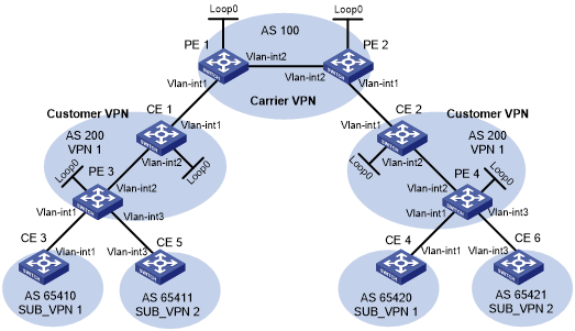
Table 19: Interface and IP address assignment
Device | Interface | IP address | Device | Interface | IP address |
|---|---|---|---|---|---|
CE 1 | Loop0 | 2.2.2.9/32 | CE 2 | Loop0 | 5.5.5.9/32 |
Vlan-int2 | 10.1.1.2/24 | Vlan-int1 | 21.1.1.2/24 | ||
Vlan-int1 | 11.1.1.1/24 | Vlan-int2 | 20.1.1.1/24 | ||
CE 3 | Vlan-int1 | 100.1.1.1/24 | CE 4 | Vlan-int1 | 120.1.1.1/24 |
CE 5 | Vlan-int3 | 110.1.1.1/24 | CE 6 | Vlan-int3 | 130.1.1.1/24 |
PE 1 | Loop0 | 3.3.3.9/32 | PE 2 | Loop0 | 4.4.4.9/32 |
Vlan-int1 | 11.1.1.2/24 | Vlan-int1 | 21.1.1.1/24 | ||
Vlan-int2 | 30.1.1.1/24 | Vlan-int2 | 30.1.1.2/24 | ||
PE 3 | Loop0 | 1.1.1.9/32 | PE 4 | Loop0 | 6.6.6.9/32 |
Vlan-int1 | 100.1.1.2/24 | Vlan-int1 | 120.1.1.2/24 | ||
Vlan-int2 | 10.1.1.1/24 | Vlan-int2 | 20.1.1.2/24 | ||
Vlan-int3 | 110.1.1.2/24 | Vlan-int3 | 130.1.1.2/24 |
Configuration procedure
Configure MPLS L3VPN on the service provider backbone. Use IS-IS as the IGP protocol, enable LDP, and establish an MP-IBGP peer relationship between PE 1 and PE 2:
# Configure PE 1.
<PE1> system-view
[PE1] interface loopback 0
[PE1-LoopBack0] ip address 3.3.3.9 32
[PE1-LoopBack0] quit
[PE1] mpls lsr-id 3.3.3.9
[PE1] mpls ldp
[PE1-ldp] quit
[PE1] isis 1
[PE1-isis-1] network-entity 10.0000.0000.0000.0004.00
[PE1-isis-1] quit
[PE1] interface loopback 0
[PE1-LoopBack0] isis enable 1
[PE1-LoopBack0] quit
[PE1] interface vlan-interface 2
[PE1-Vlan-interface2] ip address 30.1.1.1 24
[PE1-Vlan-interface2] isis enable 1
[PE1-Vlan-interface2] mpls enable
[PE1-Vlan-interface2] mpls ldp enable
[PE1-Vlan-interface2] quit
[PE1] bgp 100
[PE1-bgp-default] peer 4.4.4.9 as-number 100
[PE1-bgp-default] peer 4.4.4.9 connect-interface loopback 0
[PE1-bgp-default] address-family vpnv4
[PE1-bgp-default-vpnv4] peer 4.4.4.9 enable
[PE1-bgp-default-vpnv4] quit
[PE1-bgp-default] quit
# Configure PE 2 in the same way that PE 1 is configured. (Details not shown.)
# On PE 1 or PE 2, execute the following commands:
Execute the display mpls ldp peer command to verify that an LDP session in Operational state has been established between PE 1 and PE 2. (Details not shown.)
Execute the display bgp peer vpnv4 command to verify that a BGP peer relationship in Established state has been established between PE 1 and PE 2. (Details not shown.)
Execute the display isis peer command to verify that the IS-IS neighbor relationship has been established between PE 1 and PE 2. (Details not shown.)
Configure the customer VPN. Use IS-IS as the IGP protocol, and enable LDP between PE 3 and CE 1, and between PE 4 and CE 2:
# Configure PE 3.
<PE3> system-view
[PE3] interface loopback 0
[PE3-LoopBack0] ip address 1.1.1.9 32
[PE3-LoopBack0] quit
[PE3] mpls lsr-id 1.1.1.9
[PE3] mpls ldp
[PE3-ldp] quit
[PE3] isis 2
[PE3-isis-2] network-entity 10.0000.0000.0000.0001.00
[PE3-isis-2] quit
[PE3] interface loopback 0
[PE3-LoopBack0] isis enable 2
[PE3-LoopBack0] quit
[PE3] interface vlan-interface 2
[PE3-Vlan-interface2] ip address 10.1.1.1 24
[PE3-Vlan-interface2] isis enable 2
[PE3-Vlan-interface2] mpls enable
[PE3-Vlan-interface2] mpls ldp enable
[PE3-Vlan-interface2] quit
# Configure CE 1.
<CE1> system-view
[CE1] interface loopback 0
[CE1-LoopBack0] ip address 2.2.2.9 32
[CE1-LoopBack0] quit
[CE1] mpls lsr-id 2.2.2.9
[CE1] mpls ldp
[CE1-ldp] quit
[CE1] isis 2
[CE1-isis-2] network-entity 10.0000.0000.0000.0002.00
[CE1-isis-2] quit
[CE1] interface loopback 0
[CE1-LoopBack0] isis enable 2
[CE1-LoopBack0] quit
[CE1] interface vlan-interface 2
[CE1-Vlan-interface2] ip address 10.1.1.2 24
[CE1-Vlan-interface2] isis enable 2
[CE1-Vlan-interface2] mpls enable
[CE1-Vlan-interface2] mpls ldp enable
[CE1-Vlan-interface2] quit
An LDP session and an IS-IS neighbor relationship can be established between PE 3 and CE 1.
# Configure PE 4 and CE 2 in the same way that PE 3 and CE 1 are configured. (Details not shown.)
Connect CE 1 and CE 2 to service provider PEs:
# Configure PE 1.
[PE1] ip vpn-instance vpn1
[PE1-vpn-instance-vpn1] route-distinguisher 200:1
[PE1-vpn-instance-vpn1] vpn-target 1:1
[PE1-vpn-instance-vpn1] quit
[PE1] interface vlan-interface 1
[PE1-Vlan-interface1] ip binding vpn-instance vpn1
[PE1-Vlan-interface1] ip address 11.1.1.2 24
[PE1-Vlan-interface1] mpls enable
[PE1-Vlan-interface1] quit
[PE1] bgp 100
[PE1-bgp-default] ip vpn-instance vpn1
[PE1-bgp-default-vpn1] peer 11.1.1.1 as-number 200
[PE1-bgp-default-vpn1] address-family ipv4
[PE1-bgp-default-ipv4-vpn1] peer 11.1.1.1 enable
[PE1-bgp-default-ipv4-vpn1] quit
[PE1-bgp-default-vpn1] quit
[PE1-bgp-default] quit
# Configure CE 1.
[CE1] interface vlan-interface 1
[CE1-Vlan-interface1] ip address 11.1.1.1 24
[CE1-Vlan-interface1] mpls enable
[CE1-Vlan-interface1] quit
[CE1] bgp 200
[CE1-bgp-default] peer 11.1.1.2 as-number 100
[CE1-bgp-default-vpn1] address-family ipv4
[CE1-bgp-default-ipv4-vpn1] peer 11.1.1.2 enable
[CE1-bgp-default-ipv4-vpn1] quit
[CE1-bgp-default] quit
# Configure PE 2 and CE 2 in the same way that PE 1 and CE 1 are configured. (Details not shown.)
Connect sub-VPN CEs to the customer VPN PEs:
# Configure CE 3.
<CE3> system-view
[CE3] interface vlan-interface 1
[CE3-Vlan-interface1] ip address 100.1.1.1 24
[CE3-Vlan-interface1] quit
[CE3] bgp 65410
[CE3-bgp-default] peer 100.1.1.2 as-number 200
[CE3-bgp-default] address-family ipv4 unicast
[CE3-bgp-default-ipv4] peer 100.1.1.2 enable
[CE3-bgp-default-ipv4] import-route direct
[CE3-bgp-default-ipv4] quit
[CE3-bgp-default] quit
# Configure CE 5.
<CE5> system-view
[CE5] interface vlan-interface 3
[CE5-Vlan-interface3] ip address 110.1.1.1 24
[CE5-Vlan-interface3] quit
[CE5] bgp 65411
[CE5-bgp-default] peer 110.1.1.2 as-number 200
[CE5-bgp-default] address-family ipv4 unicast
[CE5-bgp-default-ipv4] peer 110.1.1.2 enable
[CE5-bgp-default-ipv4] import-route direct
[CE5-bgp-default-ipv4] quit
[CE5-bgp-default] quit
# Configure PE 3.
[PE3] ip vpn-instance SUB_VPN1
[PE3-vpn-instance-SUB_VPN1] route-distinguisher 100:1
[PE3-vpn-instance-SUB_VPN1] vpn-target 2:1
[PE3-vpn-instance-SUB_VPN1] quit
[PE3] interface vlan-interface 1
[PE3-Vlan-interface1] ip binding vpn-instance SUB_VPN1
[PE3-Vlan-interface1] ip address 100.1.1.2 24
[PE3-Vlan-interface1] quit
[PE3] ip vpn-instance SUB_VPN2
[PE3-vpn-instance-SUB_VPN2] route-distinguisher 101:1
[PE3-vpn-instance-SUB_VPN2] vpn-target 2:2
[PE3-vpn-instance-SUB_VPN2] quit
[PE3] interface vlan-interface 3
[PE3-Vlan-interface3] ip binding vpn-instance SUB_VPN2
[PE3-Vlan-interface3] ip address 110.1.1.2 24
[PE3-Vlan-interface3] quit
[PE3] bgp 200
[PE3-bgp-default] ip vpn-instance SUB_VPN1
[PE3-bgp-default-SUB_VPN1] peer 100.1.1.1 as-number 65410
[PE3-bgp-default-SUB_VPN1] address-family ipv4 unicast
[PE3-bgp-default-ipv4-SUB_VPN1] peer 100.1.1.1 enable
[PE3-bgp-default-ipv4-SUB_VPN1] quit
[PE3-bgp-default-SUB_VPN1] quit
[PE3-bgp-default] ip vpn-instance SUB_VPN2
[PE3-bgp-default-SUB_VPN2] peer 100.1.1.1 as-number 65411
[PE3-bgp-default-SUB_VPN2] address-family ipv4 unicast
[PE3-bgp-default-ipv4-SUB_VPN2] peer 110.1.1.1 enable
[PE3-bgp-default-ipv4-SUB_VPN2] quit
[PE3-bgp-default-SUB_VPN2] quit
[PE3-bgp-default] quit
# Configure PE 4, CE 4, and CE 6 in the same way that PE 3, CE 3, and CE 5 are configured. (Details not shown.)
Establish MP-EBGP peer relationships between service provider PEs and their CEs to exchange user VPNv4 routes:
# On PE 1, enable nested VPN and VPNv4 route exchange with CE 1.
[PE1] bgp 100
[PE1-bgp-default] address-family vpnv4
[PE1-bgp-default-vpnv4] nesting-vpn
[PE1-bgp-default-vpnv4] quit
[PE1-bgp-default] ip vpn-instance vpn1
[PE1-bgp-default-vpn1] address-family vpnv4
[PE1-bgp-default-vpnv4-vpn1] peer 11.1.1.1 enable
[PE1-bgp-default-vpnv4-vpn1] quit
[PE1-bgp-default-vpn1] quit
[PE1-bgp-default] quit
# Enable CE 1 to exchange VPNv4 routes with PE 1.
[CE1] bgp 200
[CE1-bgp-default] address-family vpnv4
[CE1-bgp-default-vpnv4] peer 11.1.1.2 enable
# Allow the local AS number to appear in the AS-PATH attribute of the routes received.
[CE1-bgp-default-vpnv4] peer 11.1.1.2 allow-as-loop 2
# Disable route target based filtering of received VPNv4 routes.
[CE1-bgp-default-vpnv4] undo policy vpn-target
[CE1-bgp-default-vpnv4] quit
[CE1-bgp-default] quit
# Configure PE 2 and CE 2 in the same way that PE 1 and CE 1 are configured. (Details not shown.)
Establish MP-IBGP peer relationships between sub-VPN PEs and CEs of the customer VPN to exchange VPNv4 routes of sub-VPNs:
# Configure PE 3.
[PE3] bgp 200
[PE3-bgp-default] peer 2.2.2.9 as-number 200
[PE3-bgp-default] peer 2.2.2.9 connect-interface loopback 0
[PE3-bgp-default] address-family vpnv4
[PE3-bgp-default-vpnv4] peer 2.2.2.9 enable
# Allow the local AS number to appear in the AS-PATH attribute of the routes received.
[PE3-bgp-default-vpnv4] peer 2.2.2.9 allow-as-loop 2
[PE3-bgp-default-vpnv4] quit
[PE3-bgp-default] quit
# Configure CE 1.
[CE1] bgp 200
[CE1-bgp-default] peer 1.1.1.9 as-number 200
[CE1-bgp-default] peer 1.1.1.9 connect-interface loopback 0
[CE1-bgp-default] address-family vpnv4
[CE1-bgp-default-vpnv4] peer 1.1.1.9 enable
[CE1-bgp-default-vpnv4] undo policy vpn-target
[CE1-bgp-default-vpnv4] quit
[CE1-bgp-default] quit
# Configure PE 4 and CE 2 in the same way that PE 3 and CE 1 are configured. (Details not shown.)
Verifying the configuration
Display the public routing table and VPN routing table on the provider PEs, for example, on PE 1:
# Verify that the public routing table contains only routes on the service provider network.
[PE1] display ip routing-table

Destinations : 14        Routes : 14

Destination/Mask   Proto   Pre Cost        NextHop         Interface
0.0.0.0/32         Direct  0   0           127.0.0.1       InLoop0
3.3.3.9/32         Direct  0   0           127.0.0.1       InLoop0
4.4.4.9/32         IS_L1   15  10          30.1.1.2        Vlan2
30.1.1.0/24        Direct  0   0           30.1.1.1        Vlan2
30.1.1.0/32        Direct  0   0           30.1.1.1        Vlan2
30.1.1.1/32        Direct  0   0           127.0.0.1       InLoop0
30.1.1.255/32      Direct  0   0           30.1.1.1        Vlan2
127.0.0.0/8        Direct  0   0           127.0.0.1       InLoop0
127.0.0.0/32       Direct  0   0           127.0.0.1       InLoop0
127.0.0.1/32       Direct  0   0           127.0.0.1       InLoop0
127.255.255.255/32 Direct  0   0           127.0.0.1       InLoop0
224.0.0.0/4        Direct  0   0           0.0.0.0         NULL0
224.0.0.0/24       Direct  0   0           0.0.0.0         NULL0
255.255.255.255/32 Direct  0   0           127.0.0.1       InLoop0
# Verify that the VPN routing table contains sub-VPN routes.
[PE1] display ip routing-table vpn-instance vpn1

Destinations : 17       Routes : 17

Destination/Mask   Proto   Pre Cost        NextHop         Interface
0.0.0.0/32         Direct  0   0           127.0.0.1       InLoop0
11.1.1.0/24        Direct  0   0           11.1.1.2        Vlan1
11.1.1.0/32        Direct  0   0           11.1.1.2        Vlan1
11.1.1.2/32        Direct  0   0           127.0.0.1       InLoop0
11.1.1.255/32      Direct  0   0           11.1.1.2        Vlan1
100.1.1.0/24       BGP     255 0           11.1.1.1        Vlan1
110.1.1.0/24       BGP     255 0           11.1.1.1        Vlan1
120.1.1.0/24       BGP     255 0           4.4.4.9         Vlan2
127.0.0.0/8        Direct  0   0           127.0.0.1       InLoop0
127.0.0.0/32       Direct  0   0           127.0.0.1       InLoop0
127.0.0.1/32       Direct  0   0           127.0.0.1       InLoop0
127.255.255.255/32 Direct  0   0           127.0.0.1       InLoop0
130.1.1.0/24       BGP     255 0           4.4.4.9         Vlan2
224.0.0.0/4        Direct  0   0           0.0.0.0         NULL0
224.0.0.0/24       Direct  0   0           0.0.0.0         NULL0
255.255.255.255/32 Direct  0   0           127.0.0.1       InLoop0
Display the VPNv4 routing table on the provider CEs, for example, on CE 1.
# Verify that the VPNv4 routing table on the customer VPN contains internal sub-VPN routes.
[CE1] display bgp routing-table vpnv4

 BGP local router ID is 2.2.2.9
 Status codes: * - valid, > - best, d - dampened, h - history,
               s - suppressed, S - stale, i - internal, e - external
               a - additional-path
               Origin: i - IGP, e - EGP, ? - incomplete

 Total number of routes from all PEs: 4

 Route distinguisher: 100:1
 Total number of routes: 1

     Network            NextHop         MED        LocPrf     PrefVal Path/Ogn

* >i 100.1.1.0/24       1.1.1.9         0          100        0       200 65410?

 Route distinguisher: 101:1
 Total number of routes: 1

     Network            NextHop         MED        LocPrf     PrefVal Path/Ogn

* >i 110.1.1.0/24       1.1.1.9         0          100        0       200 65411?

 Route distinguisher: 200:1
 Total number of routes: 1

     Network            NextHop         MED        LocPrf     PrefVal Path/Ogn

* >e 120.1.1.0/24       11.1.1.2                              0       100 200
                                                                      65420?

 Route Distinguisher: 201:1
 Total number of routes: 1

     Network            NextHop         MED        LocPrf     PrefVal Path/Ogn

* >e 130.1.1.0/24       11.1.1.2                              0       100 200
                                                                      65421?
Display the VPN routing table on the customer PEs, for example, on PE 3:
# Verify that the VPN routing table contains routes sent by the provider PE to the sub-VPN.
[PE3] display ip routing-table vpn-instance SUB_VPN1

Destinations : 11        Routes : 11

Destination/Mask   Proto   Pre Cost        NextHop         Interface
0.0.0.0/32         Direct  0   0           127.0.0.1       InLoop0
100.1.1.0/24       Direct  0   0           100.1.1.2       Vlan1
100.1.1.2/32       Direct  0   0           127.0.0.1       InLoop0
120.1.1.0/24       BGP     255 0           2.2.2.9         Vlan2
127.0.0.0/8        Direct  0   0           127.0.0.1       InLoop0
127.0.0.0/32       Direct  0   0           127.0.0.1       InLoop0
127.0.0.1/32       Direct  0   0           127.0.0.1       InLoop0
127.255.255.255/32 Direct  0   0           127.0.0.1       InLoop0
224.0.0.0/4        Direct  0   0           0.0.0.0         NULL0
224.0.0.0/24       Direct  0   0           0.0.0.0         NULL0
255.255.255.255/32 Direct  0   0           127.0.0.1       InLoop0
Display the routing table on the CEs of sub-VPNs in the customer VPN, for example, on CE 3 and CE 5:
# Verify that the routing table contains the route to the remote sub-VPN on CE 3.
[CE3] display ip routing-table

Destinations : 13        Routes : 13

Destination/Mask   Proto   Pre Cost        NextHop         Interface
0.0.0.0/32         Direct  0   0           127.0.0.1       InLoop0
100.1.1.0/24       Direct  0   0           100.1.1.1       Vlan1
100.1.1.0/32       Direct  0   0           100.1.1.1       Vlan1
100.1.1.1/32       Direct  0   0           127.0.0.1       InLoop0
100.1.1.255/32     Direct  0   0           100.1.1.1       Vlan1
120.1.1.0/24       BGP     255 0           100.1.1.2       Vlan1
127.0.0.0/8        Direct  0   0           127.0.0.1       InLoop0
127.0.0.0/32       Direct  0   0           127.0.0.1       InLoop0
127.0.0.1/32       Direct  0   0           127.0.0.1       InLoop0
127.255.255.255/32 Direct  0   0           127.0.0.1       InLoop0
224.0.0.0/4        Direct  0   0           0.0.0.0         NULL0
224.0.0.0/24       Direct  0   0           0.0.0.0         NULL0
255.255.255.255/32 Direct  0   0           127.0.0.1       InLoop0
# Verify that the routing table contains the route to the remote sub-VPN on CE 5.
[CE5] display ip routing-table

Destinations : 13        Routes : 13

Destination/Mask   Proto   Pre Cost        NextHop         Interface
0.0.0.0/32         Direct  0   0           127.0.0.1       InLoop0
110.1.1.0/24       Direct  0   0           110.1.1.1       Vlan1
110.1.1.0/32       Direct  0   0           110.1.1.1       Vlan1
110.1.1.1/32       Direct  0   0           127.0.0.1       InLoop0
110.1.1.255/32     Direct  0   0           110.1.1.1       Vlan1
127.0.0.0/8        Direct  0   0           127.0.0.1       InLoop0
127.0.0.0/32       Direct  0   0           127.0.0.1       InLoop0
127.0.0.1/32       Direct  0   0           127.0.0.1       InLoop0
127.255.255.255/32 Direct  0   0           127.0.0.1       InLoop0
130.1.1.0/24       BGP     255 0           110.1.1.2       Vlan1
224.0.0.0/4        Direct  0   0           0.0.0.0         NULL0
224.0.0.0/24       Direct  0   0           0.0.0.0         NULL0
255.255.255.255/32 Direct  0   0           127.0.0.1       InLoop0
Verify that CE 3 and CE 4 can ping each other. (Details not shown.)
Verify that CE5 and CE 6 can ping each other. (Details not shown.)
Verify that CE 3 and CE 6 cannot ping each other. (Details not shown.)