Configuring MPLS L3VPN inter-AS option A
Network requirements
CE 1 and CE 2 belong to the same VPN. CE 1 accesses the network through PE 1 in AS 100, and CE 2 accesses the network through PE 2 in AS 200.
Configure MPLS L3VPN inter-AS option A, and use the VRF-to-VRF method to manage VPN routes.
Run OSPF on the MPLS backbone in each AS.
Figure 65: Network diagram
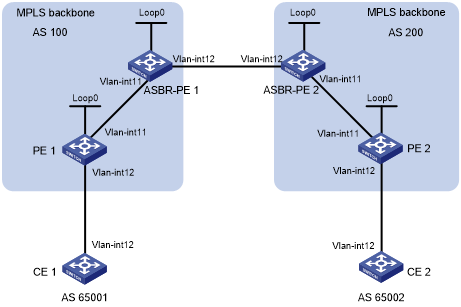
Table 14: Interface and IP address assignment
Device | Interface | IP address | Device | Interface | IP address |
|---|---|---|---|---|---|
CE 1 | Vlan-int12 | 10.1.1.1/24 | CE 2 | Vlan-int12 | 10.2.1.1/24 |
PE 1 | Loop0 | 1.1.1.9/32 | PE 2 | Loop0 | 4.4.4.9/32 |
Vlan-int12 | 10.1.1.2/24 | Vlan-int12 | 10.2.1.2/24 | ||
Vlan-int11 | 172.1.1.2/24 | Vlan-int11 | 162.1.1.2/24 | ||
ASBR-PE 1 | Loop0 | 2.2.2.9/32 | ASBR-PE 2 | Loop0 | 3.3.3.9/32 |
Vlan-int11 | 172.1.1.1/24 | Vlan-int11 | 162.1.1.1/24 | ||
Vlan-int12 | 192.1.1.1/24 | Vlan-int12 | 192.1.1.2/24 |
Configuration procedure
Configure IGP on the MPLS backbone to implement the connectivity in the backbone.
This example uses OSPF. (Details not shown.)
# Execute the display ospf peer command to verify that each ASBR-PE has established an OSPF adjacency in Full state with the PE in the same AS, and that PEs and ASBR-PEs in the same AS have learned the routes to the loopback interfaces of each other. Verify that each ASBR-PE and the PE in the same AS can ping each other. (Details not shown.)
Configure basic MPLS and MPLS LDP on the MPLS backbone to establish LDP LSPs:
# Configure basic MPLS on PE 1, and enable MPLS LDP on the interface connected to ASBR-PE 1.
<PE1> system-view
[PE1] mpls lsr-id 1.1.1.9
[PE1] mpls ldp
[PE1-ldp] quit
[PE1] interface vlan-interface 11
[PE1-Vlan-interface11] mpls enable
[PE1-Vlan-interface11] mpls ldp enable
[PE1-Vlan-interface11] quit
# Configure basic MPLS on ASBR-PE 1, and enable MPLS LDP on the interface connected to PE 1.
<ASBR-PE1> system-view
[ASBR-PE1] mpls lsr-id 2.2.2.9
[ASBR-PE1] mpls ldp
[ASBR-PE1-ldp] quit
[ASBR-PE1] interface vlan-interface 11
[ASBR-PE1-Vlan-interface11] mpls enable
[ASBR-PE1-Vlan-interface11] mpls ldp enable
[ASBR-PE1-Vlan-interface11] quit
# Configure basic MPLS on ASBR-PE 2, and enable MPLS LDP on the interface connected to PE 2.
<ASBR-PE2> system-view
[ASBR-PE2] mpls lsr-id 3.3.3.9
[ASBR-PE2] mpls ldp
[ASBR-PE2-ldp] quit
[ASBR-PE2] interface vlan-interface 11
[ASBR-PE2-Vlan-interface11] mpls enable
[ASBR-PE2-Vlan-interface11] mpls ldp enable
[ASBR-PE2-Vlan-interface11] quit
# Configure basic MPLS on PE 2, and enable MPLS LDP on the interface connected to ASBR-PE 2.
<PE2> system-view
[PE2] mpls lsr-id 4.4.4.9
[PE2] mpls ldp
[PE2-ldp] quit
[PE2] interface vlan-interface 11
[PE2-Vlan-interface11] mpls enable
[PE2-Vlan-interface11] mpls ldp enable
[PE2-Vlan-interface11] quit
# Execute the display mpls ldp peer command on the devices to verify that the session status is Operational, and that each PE and the ASBR-PE in the same AS have established a neighbor relationship. (Details not shown.)
Configure VPN instances on PEs:
For the same VPN, the route targets for the VPN instance on the PE must match those for the VPN instance on the ASBR-PE in the same AS. This is not required for PEs in different ASs.
# Configure CE 1.
<CE1> system-view
[CE1] interface vlan-interface 12
[CE1-Vlan-interface12] ip address 10.1.1.1 24
[CE1-Vlan-interface12] quit
# Configure PE 1.
[PE1] ip vpn-instance vpn1
[PE1-vpn-instance-vpn1] route-distinguisher 100:1
[PE1-vpn-instance-vpn1] vpn-target 100:1 both
[PE1-vpn-instance-vpn1] quit
[PE1] interface vlan-interface 12
[PE1-Vlan-interface12] ip binding vpn-instance vpn1
[PE1-Vlan-interface12] ip address 10.1.1.2 24
[PE1-Vlan-interface12] quit
# Configure CE 2.
<CE2> system-view
[CE2] interface vlan-interface 12
[CE2-Vlan-interface12] ip address 10.2.1.1 24
[CE2-Vlan-interface12] quit
# Configure PE 2.
[PE2] ip vpn-instance vpn1
[PE2-vpn-instance] route-distinguisher 200:2
[PE2-vpn-instance] vpn-target 200:1 both
[PE2-vpn-instance] quit
[PE2] interface vlan-interface 12
[PE2-Vlan-interface12] ip binding vpn-instance vpn1
[PE2-Vlan-interface12] ip address 10.2.1.2 24
[PE2-Vlan-interface12] quit
# On ASBR-PE 1, create a VPN instance, and bind the instance to the interface connected to ASBR-PE 2. ASBR-PE 1 considers ASBR-PE 2 to be its CE.
[ASBR-PE1] ip vpn-instance vpn1
[ASBR-PE1-vpn-instance-vpn1] route-distinguisher 100:1
[ASBR-PE1-vpn-instance-vpn1] vpn-target 100:1 both
[ASBR-PE1-vpn-instance-vpn1] quit
[ASBR-PE1] interface vlan-interface 12
[ASBR-PE1-Vlan-interface12] ip binding vpn-instance vpn1
[ASBR-PE1-Vlan-interface12] ip address 192.1.1.1 24
[ASBR-PE1-Vlan-interface12] quit
# On ASBR-PE 2, create a VPN instance, and bind the instance to the interface connected to ASBR-PE 1. ASBR-PE 2 considers ASBR-PE 1 to be its CE.
[ASBR-PE2] ip vpn-instance vpn1
[ASBR-PE2-vpn-vpn-vpn1] route-distinguisher 200:1
[ASBR-PE2-vpn-vpn-vpn1] vpn-target 200:1 both
[ASBR-PE2-vpn-vpn-vpn1] quit
[ASBR-PE2] interface vlan-interface 12
[ASBR-PE2-Vlan-interface12] ip binding vpn-instance vpn1
[ASBR-PE2-Vlan-interface12] ip address 192.1.1.2 24
[ASBR-PE2-Vlan-interface12] quit
# Execute the display ip vpn-instance command to display VPN instance configurations. Verify that the PEs can ping the CEs, and the ASBR-PEs can ping each other. (Details not shown.)
Establish EBGP peer relationships between PEs and CEs, and redistribute VPN routes into BGP:
# Configure CE 1.
[CE1] bgp 65001
[CE1-bgp-default] peer 10.1.1.2 as-number 100
[CE1-bgp-default] address-family ipv4 unicast
[CE1-bgp-default-ipv4] peer 10.1.1.2 enable
[CE1-bgp-default-ipv4] import-route direct
[CE1-bgp-default-ipv4] quit
[CE1-bgp-default] quit
# Configure PE 1.
[PE1] bgp 100
[PE1-bgp-default] ip vpn-instance vpn1
[PE1-bgp-default-vpn1] peer 10.1.1.1 as-number 65001
[PE1-bgp-default-vpn1] address-family ipv4 unicast
[PE1-bgp-default-ipv4-vpn1] peer 10.1.1.1 enable
[PE1-bgp-default-ipv4-vpn1] quit
[PE1-bgp-default-vpn1] quit
[PE1-bgp-default] quit
# Configure CE 2.
[CE2] bgp 65002
[CE2-bgp-default] peer 10.2.1.2 as-number 200
[CE2-bgp-default] address-family ipv4 unicast
[CE2-bgp-default-ipv4] peer 10.2.1.2 enable
[CE2-bgp-default-ipv4] import-route direct
[CE2-bgp-default-ipv4] quit
[CE2-bgp-default] quit
# Configure PE 2.
[PE2] bgp 200
[PE2-bgp-default] ip vpn-instance vpn1
[PE2-bgp-default-vpn1] peer 10.2.1.1 as-number 65002
[PE2-bgp-default-vpn1] address-family ipv4 unicast
[PE2-bgp-default-ipv4-vpn1] peer 10.2.1.1 enable
[PE2-bgp-default-ipv4-vpn1] quit
[PE2-bgp-default-vpn1] quit
[PE2-bgp-default] quit
Establish an MP-IBGP peer relationship between each PE and the ASBR-PE in the same AS, and an EBGP peer relationship between the ASBR-PEs:
# Configure PE 1.
[PE1] bgp 100
[PE1-bgp-default] peer 2.2.2.9 as-number 100
[PE1-bgp-default] peer 2.2.2.9 connect-interface loopback 0
[PE1-bgp-default] address-family vpnv4
[PE1-bgp-default-vpnv4] peer 2.2.2.9 enable
[PE1-bgp-default-vpnv4] peer 2.2.2.9 next-hop-local
[PE1-bgp-default-vpnv4] quit
[PE1-bgp-default] quit
# Configure ASBR-PE 1.
[ASBR-PE1] bgp 100
[ASBR-PE1-bgp-default] ip vpn-instance vpn1
[ASBR-PE1-bgp-default-vpn1] peer 192.1.1.2 as-number 200
[ASBR-PE1-bgp-default-vpn1] address-family ipv4 unicast
[ASBR-PE1-bgp-default-ipv4-vpn1] peer 192.1.1.2 enable
[ASBR-PE1-bgp-default-ipv4-vpn1] quit
[ASBR-PE1-bgp-default-vpn1] quit
[ASBR-PE1-bgp-default] peer 1.1.1.9 as-number 100
[ASBR-PE1-bgp-default] peer 1.1.1.9 connect-interface loopback 0
[ASBR-PE1-bgp-default] address-family vpnv4
[ASBR-PE1-bgp-default-vpnv4] peer 1.1.1.9 enable
[ASBR-PE1-bgp-default-vpnv4] peer 1.1.1.9 next-hop-local
[ASBR-PE1-bgp-default-vpnv4] quit
[ASBR-PE1-bgp-default] quit
# Configure ASBR-PE 2.
[ASBR-PE2] bgp 200
[ASBR-PE2-bgp-default] ip vpn-instance vpn1
[ASBR-PE2-bgp-default-vpn1] peer 192.1.1.1 as-number 100
[ASBR-PE2-bgp-default-vpn1] address-family ipv4 unicast
[ASBR-PE2-bgp-default-ipv4-vpn1] peer 192.1.1.1 enable
[ASBR-PE2-bgp-default-ipv4-vpn1] quit
[ASBR-PE2-bgp-default-vpn1] quit
[ASBR-PE2-bgp-default] peer 4.4.4.9 as-number 200
[ASBR-PE2-bgp-default] peer 4.4.4.9 connect-interface loopback 0
[ASBR-PE2-bgp-default] address-family vpnv4
[ASBR-PE2-bgp-default-vpnv4] peer 4.4.4.9 enable
[ASBR-PE2-bgp-default-vpnv4] peer 4.4.4.9 next-hop-local
[ASBR-PE2-bgp-default-vpnv4] quit
[ASBR-PE2-bgp-default] quit
# Configure PE 2.
[PE2] bgp 200
[PE2-bgp-default] peer 3.3.3.9 as-number 200
[PE2-bgp-default] peer 3.3.3.9 connect-interface loopback 0
[PE2-bgp-default] address-family vpnv4
[PE2-bgp-default-vpnv4] peer 3.3.3.9 enable
[PE2-bgp-default-vpnv4] peer 3.3.3.9 next-hop-local
[PE2-bgp-default-vpnv4] quit
[PE2-bgp-default] quit
Verifying the configuration
# Verify that the CEs can learn the interface routes from each other and ping each other. (Details not shown.)