Configuring a hub-spoke network
Network requirements
The Spoke-CEs cannot communicate directly. They can communicate only through Hub-CE.
Configure EBGP between the Spoke-CEs and Spoke-PEs and between Hub-CE and Hub-PE to exchange VPN routing information.
Configure OSPF between the Spoke-PEs and Hub-PE to implement communication between the PEs, and configure MP-IBGP between them to exchange VPN routing information.
Figure 64: Network diagram
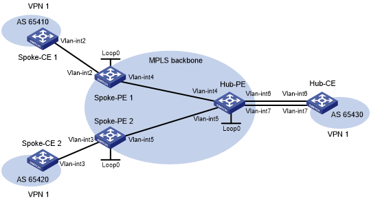
Table 13: Interface and IP address assignment
Device | Interface | IP address | Device | Interface | IP address |
|---|---|---|---|---|---|
Spoke-CE 1 | Vlan-int2 | 10.1.1.1/24 | Hub-CE | Vlan-int6 | 10.3.1.1/24 |
Spoke-PE 1 | Loop0 | 1.1.1.9/32 | Vlan-int7 | 10.4.1.1/24 | |
Vlan-int2 | 10.1.1.2/24 | Hub-PE | Loop0 | 2.2.2.9/32 | |
Vlan-int4 | 172.1.1.1/24 | Vlan-int4 | 172.1.1.2/24 | ||
Spoke-CE 2 | Vlan-int3 | 10.2.1.1/24 | Vlan-int5 | 172.2.1.2/24 | |
Spoke-PE 2 | Loop0 | 3.3.3.9/32 | Vlan-int6 | 10.3.1.2/24 | |
Vlan-int3 | 10.2.1.2/24 | Vlan-int7 | 10.4.1.2/24 | ||
Vlan-int5 | 172.2.1.1/24 |
Configuration procedure
Configure an IGP on the MPLS backbone to ensure IP connectivity within the backbone:
# Configure Spoke-PE 1.
<Spoke-PE1> system-view
[Spoke-PE1] interface loopback 0
[Spoke-PE1-LoopBack0] ip address 1.1.1.9 32
[Spoke-PE1-LoopBack0] quit
[Spoke-PE1] interface vlan-interface 4
[Spoke-PE1-Vlan-interface4] ip address 172.1.1.1 24
[Spoke-PE1-Vlan-interface4] quit
[Spoke-PE1] ospf
[Spoke-PE1-ospf-1] area 0
[Spoke-PE1-ospf-1-area-0.0.0.0] network 172.1.1.0 0.0.0.255
[Spoke-PE1-ospf-1-area-0.0.0.0] network 1.1.1.9 0.0.0.0
[Spoke-PE1-ospf-1-area-0.0.0.0] quit
[Spoke-PE1-ospf-1] quit
# Configure Spoke-PE 2.
<Spoke-PE2> system-view
[Spoke-PE2] interface loopback 0
[Spoke-PE2-LoopBack0] ip address 3.3.3.9 32
[Spoke-PE2-LoopBack0] quit
[Spoke-PE2] interface vlan-interface 5
[Spoke-PE2-Vlan-interface5] ip address 172.2.1.1 24
[Spoke-PE2-Vlan-interface5] quit
[Spoke-PE2] ospf
[Spoke-PE2-ospf-1] area 0
[Spoke-PE2-ospf-1-area-0.0.0.0] network 172.2.1.0 0.0.0.255
[Spoke-PE2-ospf-1-area-0.0.0.0] network 3.3.3.9 0.0.0.0
[Spoke-PE2-ospf-1-area-0.0.0.0] quit
[Spoke-PE2-ospf-1] quit
# Configure Hub-PE.
<Hub-PE> system-view
[Hub-PE] interface loopback 0
[Hub-PE-LoopBack0] ip address 2.2.2.9 32
[Hub-PE-LoopBack0] quit
[Hub-PE] interface vlan-interface 4
[Hub-PE-Vlan-interface4] ip address 172.1.1.2 24
[Hub-PE-Vlan-interface4] quit
[Hub-PE] interface vlan-interface 5
[Hub-PE-Vlan-interface5] ip address 172.2.1.2 24
[Hub-PE-Vlan-interface5] quit
[Hub-PE] ospf
[Hub-PE-ospf-1] area 0
[Hub-PE-ospf-1-area-0.0.0.0] network 172.1.1.0 0.0.0.255
[Hub-PE-ospf-1-area-0.0.0.0] network 172.2.1.0 0.0.0.255
[Hub-PE-ospf-1-area-0.0.0.0] network 2.2.2.9 0.0.0.0
[Hub-PE-ospf-1-area-0.0.0.0] quit
[Hub-PE-ospf-1] quit
# Execute the display ospf peer command on the devices to verify that OSPF adjacencies in Full state have been established between Spoke-PE 1, Spoke-PE 2, and Hub-PE. Execute the display ip routing-table command on the devices to verify that the PEs have learned the routes to the loopback interfaces of each other. (Details not shown.)
Configure basic MPLS and MPLS LDP on the MPLS backbone to establish LDP LSPs:
# Configure Spoke-PE 1.
[Spoke-PE1] mpls lsr-id 1.1.1.9
[Spoke-PE1] mpls ldp
[Spoke-PE1-ldp] quit
[Spoke-PE1] interface vlan-interface 4
[Spoke-PE1-Vlan-interface4] mpls enable
[Spoke-PE1-Vlan-interface4] mpls ldp enable
[Spoke-PE1-Vlan-interface4] quit
# Configure Spoke-PE 2.
[Spoke-PE2] mpls lsr-id 3.3.3.9
[Spoke-PE2] mpls ldp
[Spoke-PE2-ldp] quit
[Spoke-PE2] interface vlan-interface 5
[Spoke-PE2-Vlan-interface5] mpls enable
[Spoke-PE2-Vlan-interface5] mpls ldp enable
[Spoke-PE2-Vlan-interface5] quit
# Configure Hub-PE.
[Hub-PE] mpls lsr-id 2.2.2.9
[Hub-PE] mpls ldp
[Hub-PE-ldp] quit
[Hub-PE] interface vlan-interface 4
[Hub-PE-Vlan-interface4] mpls enable
[Hub-PE-Vlan-interface4] mpls ldp enable
[Hub-PE-Vlan-interface4] quit
[Hub-PE] interface vlan-interface 5
[Hub-PE-Vlan-interface5] mpls enable
[Hub-PE-Vlan-interface5] mpls ldp enable
[Hub-PE-Vlan-interface5] quit
# Execute the display mpls ldp peer command on the devices to verify that LDP sessions in Operational state have been established between Spoke-PE 1, Spoke-PE 2, and Hub-PE. Execute the display mpls ldp lsp command on the devices to verify that the LSPs have been established by LDP. (Details not shown.)
Configure VPN instances on the Spoke-PEs and Hub-PE:
# Configure Spoke-PE 1.
[Spoke-PE1] ip vpn-instance vpn1
[Spoke-PE1-vpn-instance-vpn1] route-distinguisher 100:1
[Spoke-PE1-vpn-instance-vpn1] vpn-target 111:1 import-extcommunity
[Spoke-PE1-vpn-instance-vpn1] vpn-target 222:2 export-extcommunity
[Spoke-PE1-vpn-instance-vpn1] quit
[Spoke-PE1] interface vlan-interface 2
[Spoke-PE1-Vlan-interface2] ip binding vpn-instance vpn1
[Spoke-PE1-Vlan-interface2] ip address 10.1.1.2 24
[Spoke-PE1-Vlan-interface2] quit
# Configure Spoke-PE 2.
[Spoke-PE2] ip vpn-instance vpn1
[Spoke-PE2-vpn-instance-vpn1] route-distinguisher 100:2
[Spoke-PE2-vpn-instance-vpn1] vpn-target 111:1 import-extcommunity
[Spoke-PE2-vpn-instance-vpn1] vpn-target 222:2 export-extcommunity
[Spoke-PE2-vpn-instance-vpn1] quit
[Spoke-PE2] interface vlan-interface 3
[Spoke-PE2-Vlan-interface3] ip binding vpn-instance vpn1
[Spoke-PE2-Vlan-interface3] ip address 10.2.1.2 24
[Spoke-PE2-Vlan-interface3] quit
# Configure Hub-PE.
[Hub-PE] ip vpn-instance vpn1-in
[Hub-PE-vpn-instance-vpn1-in] route-distinguisher 100:3
[Hub-PE-vpn-instance-vpn1-in] vpn-target 222:2 import-extcommunity
[Hub-PE-vpn-instance-vpn1-in] quit
[Hub-PE] ip vpn-instance vpn1-out
[Hub-PE-vpn-instance-vpn1-out] route-distinguisher 100:4
[Hub-PE-vpn-instance-vpn1-out] vpn-target 111:1 export-extcommunity
[Hub-PE-vpn-instance-vpn1-out] quit
[Hub-PE] interface vlan-interface 6
[Hub-PE-Vlan-interface6] ip binding vpn-instance vpn1-in
[Hub-PE-Vlan-interface6] ip address 10.3.1.2 24
[Hub-PE-Vlan-interface6] quit
[Hub-PE] interface vlan-interface 7
[Hub-PE-Vlan-interface7] ip binding vpn-instance vpn1-out
[Hub-PE-Vlan-interface7] ip address 10.4.1.2 24
[Hub-PE-Vlan-interface7] quit
# Configure IP addresses for the CEs according to Table 13. (Details not shown.)
# Execute the display ip vpn-instance command on the PEs to display the configuration of the VPN instance, for example, on Spoke-PE 1.
[Spoke-PE1] display ip vpn-instance
  Total VPN-Instances configured : 1

  VPN-Instance Name               RD                     Create time
  vpn1                            100:1                  2009/04/08 10:55:07
# Use the ping command on the PEs to verify that the PEs can ping their attached CEs, for example, on Spoke-PE 1.
[Spoke-PE1] ping -vpn-instance vpn1 10.1.1.1
Ping 10.1.1.1 (10.1.1.1): 56 data bytes, press CTRL_C to break
56 bytes from 10.1.1.1: icmp_seq=0 ttl=128 time=1.913 ms
56 bytes from 10.1.1.1: icmp_seq=1 ttl=128 time=2.381 ms
56 bytes from 10.1.1.1: icmp_seq=2 ttl=128 time=1.707 ms
56 bytes from 10.1.1.1: icmp_seq=3 ttl=128 time=1.666 ms
56 bytes from 10.1.1.1: icmp_seq=4 ttl=128 time=2.710 ms

--- Ping statistics for 10.1.1.1 ---
5 packet(s) transmitted, 5 packet(s) received, 0.0% packet loss
round-trip min/avg/max/std-dev = 1.666/2.075/2.710/0.406 ms
Establish EBGP peer relationships between the PEs and CEs, and redistribute VPN routes into BGP:
# Configure Spoke-CE 1.
<Spoke-CE1> system-view
[Spoke-CE1] bgp 65410
[Spoke-CE1-bgp-default] peer 10.1.1.2 as-number 100
[Spoke-CE1-bgp-default] address-family ipv4
[Spoke-CE1-bgp-default-ipv4] peer 10.1.1.2 enable
[Spoke-CE1-bgp-default-ipv4] import-route direct
[Spoke-CE1-bgp-default-ipv4] quit
[Spoke-CE1-bgp-default] quit
# Configure Spoke-CE 2.
<Spoke-CE2> system-view
[Spoke-CE2] bgp 65420
[Spoke-CE2-bgp-default] peer 10.2.1.2 as-number 100
[Spoke-CE2-bgp-default] address-family ipv4
[Spoke-CE2-bgp-default-ipv4] peer 10.2.1.2 enable
[Spoke-CE2-bgp-default-ipv4] import-route direct
[Spoke-CE2-bgp-default-ipv4] quit
[Spoke-CE2-bgp-default] quit
# Configure Hub-CE.
<Hub-CE> system-view
[Hub-CE] bgp 65430
[Hub-CE-bgp-default] peer 10.3.1.2 as-number 100
[Hub-CE-bgp-default] peer 10.4.1.2 as-number 100
[Hub-CE-bgp-default] address-family ipv4
[Hub-CE-bgp-default-ipv4] peer 10.3.1.2 enable
[Hub-CE-bgp-default-ipv4] peer 10.4.1.2 enable
[Hub-CE-bgp-default-ipv4] import-route direct
[Hub-CE-bgp-default-ipv4] quit
[Hub-CE-bgp-default] quit
# Configure Spoke-PE 1.
[Spoke-PE1] bgp 100
[Spoke-PE1-bgp-default] ip vpn-instance vpn1
[Spoke-PE1-bgp-default-vpn1] peer 10.1.1.1 as-number 65410
[Spoke-PE1-bgp-default-vpn1] address-family ipv4
[Spoke-PE1-bgp-default-ipv4-vpn1] peer 10.1.1.1 enable
[Spoke-PE1-bgp-default-ipv4-vpn1] quit
[Spoke-PE1-bgp-default-vpn1] quit
[Spoke-PE1-bgp-default] quit
# Configure Spoke-PE 2.
[Spoke-PE2] bgp 100
[Spoke-PE2-bgp-default] ip vpn-instance vpn1
[Spoke-PE2-bgp-default-vpn1] peer 10.2.1.1 as-number 65420
[Spoke-PE2-bgp-default-vpn1] address-family ipv4
[Spoke-PE2-bgp-default-ipv4-vpn1] peer 10.2.1.1 enable
[Spoke-PE2-bgp-default-ipv4-vpn1] quit
[Spoke-PE2-bgp-default-vpn1] quit
[Spoke-PE2-bgp-default] quit
# Configure Hub-PE.
[Hub-PE] bgp 100
[Hub-PE-bgp-default] ip vpn-instance vpn1-in
[Hub-PE-bgp-default-vpn1-in] peer 10.3.1.1 as-number 65430
[Hub-PE-bgp-default-vpn1-in] address-family ipv4
[Hub-PE-bgp-default-ipv4-vpn1-in] peer 10.3.1.1 enable
[Hub-PE-bgp-default-ipv4-vpn1-in] quit
[Hub-PE-bgp-default-vpn1-in] quit
[Hub-PE-bgp-default] ip vpn-instance vpn1-out
[Hub-PE-bgp-default-vpn1-out] peer 10.4.1.1 as-number 65430
[Hub-PE-bgp-default-vpn1-out] address-family ipv4
[Hub-PE-bgp-default-ipv4-vpn1-out] peer 10.4.1.1 enable
[Hub-PE-bgp-default-ipv4-vpn1-out] peer 10.4.1.1 allow-as-loop 2
[Hub-PE-bgp-default-ipv4-vpn1-out] quit
[Hub-PE-bgp-default-vpn1-out] quit
[Hub-PE-bgp-default] quit
# Execute the display bgp peer ipv4 vpn-instance command on the PEs to verify that a BGP peer relationship in Established state has been established between a PE and a CE. (Details not shown.)
Establish an MP-IBGP peer relationship between the Spoke-PEs and Hub-PE:
# Configure Spoke-PE 1.
[Spoke-PE1] bgp 100
[Spoke-PE1-bgp-default] peer 2.2.2.9 as-number 100
[Spoke-PE1-bgp-default] peer 2.2.2.9 connect-interface loopback 0
[Spoke-PE1-bgp-default] address-family vpnv4
[Spoke-PE1-bgp-default-vpnv4] peer 2.2.2.9 enable
[Spoke-PE1-bgp-default-vpnv4] quit
[Spoke-PE1-bgp-default] quit
# Configure Spoke-PE 2.
[Spoke-PE2] bgp 100
[Spoke-PE2-bgp-default] peer 2.2.2.9 as-number 100
[Spoke-PE2-bgp-default] peer 2.2.2.9 connect-interface loopback 0
[Spoke-PE2-bgp-default] address-family vpnv4
[Spoke-PE2-bgp-default-vpnv4] peer 2.2.2.9 enable
[Spoke-PE2-bgp-default-vpnv4] quit
[Spoke-PE2-bgp-default] quit
# Configure Hub-PE.
[Hub-PE] bgp 100
[Hub-PE-bgp-default] peer 1.1.1.9 as-number 100
[Hub-PE-bgp-default] peer 1.1.1.9 connect-interface loopback 0
[Hub-PE-bgp-default] peer 3.3.3.9 as-number 100
[Hub-PE-bgp-default] peer 3.3.3.9 connect-interface loopback 0
[Hub-PE-bgp-default] address-family vpnv4
[Hub-PE-bgp-default-vpnv4] peer 1.1.1.9 enable
[Hub-PE-bgp-default-vpnv4] peer 3.3.3.9 enable
[Hub-PE-bgp-default-vpnv4] quit
[Hub-PE-bgp-default] quit
# Execute the display bgp peer vpnv4 command on the PEs to verify that a BGP peer relationship in Established state has been established between the PEs. (Details not shown.)
Verifying the configuration
# Execute the display ip routing-table vpn-instance command on the PEs to display the routes to the CEs. This example uses Spoke-PE 1 to verify that the next hop of the route from a Spoke-PE to its connected Spoke-CE is Hub-PE.
[Spoke-PE1] display ip routing-table vpn-instance vpn1

Destinations : 15        Routes : 15

Destination/Mask   Proto   Pre Cost        NextHop         Interface
0.0.0.0/32         Direct  0   0           127.0.0.1       InLoop0
10.1.1.0/24        Direct  0   0           10.1.1.2        Vlan2
10.1.1.0/32        Direct  0   0           10.1.1.2        Vlan2
10.1.1.2/32        Direct  0   0           127.0.0.1       InLoop0
10.1.1.255/32      Direct  0   0           10.1.1.2        Vlan2
10.2.1.0/24        BGP     255 0           2.2.2.9         Vlan4
10.3.1.0/24        BGP     255 0           2.2.2.9         Vlan4
10.4.1.0/24        BGP     255 0           2.2.2.9         Vlan4
127.0.0.0/8        Direct  0   0           127.0.0.1       InLoop0
127.0.0.0/32       Direct  0   0           127.0.0.1       InLoop0
127.0.0.1/32       Direct  0   0           127.0.0.1       InLoop0
127.255.255.255/32 Direct  0   0           127.0.0.1       InLoop0
224.0.0.0/4        Direct  0   0           0.0.0.0         NULL0
224.0.0.0/24       Direct  0   0           0.0.0.0         NULL0
255.255.255.255/32 Direct  0   0           127.0.0.1       InLoop0
# Verify that Spoke-CE 1 and Spoke-CE 2 can ping each other. The TTL value indicates that traffic from Spoke-CE 1 to Spoke-CE 2 passes six hops (255-250+1) and is forwarded through Hub-CE. This example uses Spoke-CE 1 to verify their connectivity.
[Spoke-CE1] ping 10.2.1.1
Ping 10.2.1.1 (10.2.1.1): 56 data bytes, press CTRL_C to break
56 bytes from 10.2.1.1: icmp_seq=0 ttl=250 time=1.000 ms
56 bytes from 10.2.1.1: icmp_seq=1 ttl=250 time=2.000 ms
56 bytes from 10.2.1.1: icmp_seq=2 ttl=250 time=0.000 ms
56 bytes from 10.2.1.1: icmp_seq=3 ttl=250 time=1.000 ms
56 bytes from 10.2.1.1: icmp_seq=4 ttl=250 time=0.000 ms

--- Ping statistics for 10.2.1.1 ---
5 packet(s) transmitted, 5 packet(s) received, 0.0% packet loss
round-trip min/avg/max/std-dev = 0.000/0.800/2.000/0.748 ms