Configuring basic MPLS L3VPN
Network requirements
CE 1 and CE 3 belong to VPN 1. CE 2 and CE 4 belong to VPN 2.
VPN 1 uses route target attribute 111:1. VPN 2 uses route target attribute 222:2. Users of different VPNs cannot access each other.
EBGP is used to exchange VPN routing information between CE and PE.
PEs use OSPF to communicate with each other and use MP-IBGP to exchange VPN routing information.
Figure 63: Network diagram
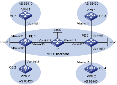
Table 12: Interface and IP address assignment
Device | Interface | IP address | Device | Interface | IP address |
|---|---|---|---|---|---|
CE 1 | Vlan-int11 | 10.1.1.1/24 | P | Loop0 | 2.2.2.9/32 |
PE 1 | Loop0 | 1.1.1.9/32 | Vlan-int12 | 172.2.1.1/24 | |
Vlan-int11 | 10.1.1.2/24 | Vlan-int13 | 172.1.1.2/24 | ||
Vlan-int13 | 172.1.1.1/24 | PE 2 | Loop0 | 3.3.3.9/32 | |
Vlan-int12 | 10.2.1.2/24 | Vlan-int12 | 172.2.1.2/24 | ||
CE 2 | Vlan-int12 | 10.2.1.1/24 | Vlan-int11 | 10.3.1.2/24 | |
CE 3 | Vlan-int11 | 10.3.1.1/24 | Vlan-int13 | 10.4.1.2/24 | |
CE 4 | Vlan-int13 | 10.4.1.1/24 |
Configuration procedure
Configure an IGP on the MPLS backbone to ensure IP connectivity within the backbone:
# Configure PE 1.
<PE1> system-view
[PE1] interface loopback 0
[PE1-LoopBack0] ip address 1.1.1.9 32
[PE1-LoopBack0] quit
[PE1] interface vlan-interface 13
[PE1-Vlan-interface13] ip address 172.1.1.1 24
[PE1-Vlan-interface13] quit
[PE1] ospf
[PE1-ospf-1] area 0
[PE1-ospf-1-area-0.0.0.0] network 172.1.1.0 0.0.0.255
[PE1-ospf-1-area-0.0.0.0] network 1.1.1.9 0.0.0.0
[PE1-ospf-1-area-0.0.0.0] quit
[PE1-ospf-1] quit
# Configure the P device.
<P> system-view
[P] interface loopback 0
[P-LoopBack0] ip address 2.2.2.9 32
[P-LoopBack0] quit
[P] interface vlan-interface 13
[P-Vlan-interface13] ip address 172.1.1.2 24
[P-Vlan-interface13] quit
[P] interface vlan-interface 12
[P-Vlan-interface12] ip address 172.2.1.1 24
[P-Vlan-interface12] quit
[P] ospf
[P-ospf-1] area 0
[P-ospf-1-area-0.0.0.0] network 172.1.1.0 0.0.0.255
[P-ospf-1-area-0.0.0.0] network 172.2.1.0 0.0.0.255
[P-ospf-1-area-0.0.0.0] network 2.2.2.9 0.0.0.0
[P-ospf-1-area-0.0.0.0] quit
[P-ospf-1] quit
# Configure PE 2.
<PE2> system-view
[PE2] interface loopback 0
[PE2-LoopBack0] ip address 3.3.3.9 32
[PE2-LoopBack0] quit
[PE2] interface vlan-interface 12
[PE2-Vlan-interface12] ip address 172.2.1.2 24
[PE2-Vlan-interface12] quit
[PE2] ospf
[PE2-ospf-1] area 0
[PE2-ospf-1-area-0.0.0.0] network 172.2.1.0 0.0.0.255
[PE2-ospf-1-area-0.0.0.0] network 3.3.3.9 0.0.0.0
[PE2-ospf-1-area-0.0.0.0] quit
[PE2-ospf-1] quit
# Execute the display ospf peer command to verify that OSPF adjacencies in Full state have been established between PE 1, P, and PE 2. Execute the display ip routing-table command to verify that the PEs have learned the routes to the loopback interfaces of each other. (Details not shown.)
Configure basic MPLS and MPLS LDP on the MPLS backbone to establish LDP LSPs:
# Configure PE 1.
[PE1] mpls lsr-id 1.1.1.9
[PE1] mpls ldp
[PE1-ldp] quit
[PE1] interface vlan-interface 13
[PE1-Vlan-interface13] mpls enable
[PE1-Vlan-interface13] mpls ldp enable
[PE1-Vlan-interface13] quit
# Configure the P device.
[P] mpls lsr-id 2.2.2.9
[P] mpls ldp
[P-ldp] quit
[P] interface vlan-interface 13
[P-Vlan-interface13] mpls enable
[P-Vlan-interface13] mpls ldp enable
[P-Vlan-interface13] quit
[P] interface vlan-interface 12
[P-Vlan-interface12] mpls enable
[P-Vlan-interface12] mpls ldp enable
[P-Vlan-interface12] quit
# Configure PE 2.
[PE2] mpls lsr-id 3.3.3.9
[PE2] mpls ldp
[PE2-ldp] quit
[PE2] interface vlan-interface 12
[PE2-Vlan-interface12] mpls enable
[PE2-Vlan-interface12] mpls ldp enable
[PE2-Vlan-interface12] quit
# Execute the display mpls ldp peer command to verify that LDP sessions in Operational state have been established between PE 1, P, and PE 2. Execute the display mpls ldp lsp command to verify that the LSPs have been established by LDP. (Details not shown.)
Configure VPN instances on PEs:
# Configure PE 1.
[PE1] ip vpn-instance vpn1
[PE1-vpn-instance-vpn1] route-distinguisher 100:1
[PE1-vpn-instance-vpn1] vpn-target 111:1
[PE1-vpn-instance-vpn1] quit
[PE1] ip vpn-instance vpn2
[PE1-vpn-instance-vpn2] route-distinguisher 100:2
[PE1-vpn-instance-vpn2] vpn-target 222:2
[PE1-vpn-instance-vpn2] quit
[PE1] interface vlan-interface 11
[PE1-Vlan-interface11] ip binding vpn-instance vpn1
[PE1-Vlan-interface11] ip address 10.1.1.2 24
[PE1-Vlan-interface11] quit
[PE1] interface vlan-interface 12
[PE1-Vlan-interface12] ip binding vpn-instance vpn2
[PE1-Vlan-interface12] ip address 10.2.1.2 24
[PE1-Vlan-interface12] quit
# Configure PE 2.
[PE2] ip vpn-instance vpn1
[PE2-vpn-instance-vpn1] route-distinguisher 200:1
[PE2-vpn-instance-vpn1] vpn-target 111:1
[PE2-vpn-instance-vpn1] quit
[PE2] ip vpn-instance vpn2
[PE2-vpn-instance-vpn2] route-distinguisher 200:2
[PE2-vpn-instance-vpn2] vpn-target 222:2
[PE2-vpn-instance-vpn2] quit
[PE2] interface vlan-interface 11
[PE2-Vlan-interface11] ip binding vpn-instance vpn1
[PE2-Vlan-interface11] ip address 10.3.1.2 24
[PE2-Vlan-interface11] quit
[PE2] interface vlan-interface 13
[PE2-Vlan-interface13] ip binding vpn-instance vpn2
[PE2-Vlan-interface13] ip address 10.4.1.2 24
[PE2-Vlan-interface13] quit
# Configure IP addresses for the CEs according to Figure 63. (Details not shown.)
# Execute the display ip vpn-instance command on the PEs to display the configuration of the VPN instance, for example, on PE 1.
[PE1] display ip vpn-instance
  Total VPN-Instances configured : 2
  VPN-Instance Name               RD                     Create time
  vpn1                            100:1                  2012/02/13 12:49:08
  vpn2                            100:2                  2012/02/13 12:49:20
# Use the ping command on the PEs to verify that the PEs can ping their attached CEs, for example, on PE 1.
[PE1] ping -vpn-instance vpn1 10.1.1.1
Ping 10.1.1.1 (10.1.1.1): 56 data bytes, press CTRL_C to break
56 bytes from 10.1.1.1: icmp_seq=0 ttl=255 time=1.000 ms
56 bytes from 10.1.1.1: icmp_seq=1 ttl=255 time=2.000 ms
56 bytes from 10.1.1.1: icmp_seq=2 ttl=255 time=0.000 ms
56 bytes from 10.1.1.1: icmp_seq=3 ttl=255 time=1.000 ms
56 bytes from 10.1.1.1: icmp_seq=4 ttl=255 time=0.000 ms

--- Ping statistics for 10.1.1.1 ---
5 packet(s) transmitted, 5 packet(s) received, 0.0% packet loss
round-trip min/avg/max/std-dev = 0.000/0.800/2.000/0.748 ms
Establish EBGP peer relationships between PEs and CEs, and redistribute VPN routes into BGP:
# Configure CE 1.
<CE1> system-view
[CE1] bgp 65410
[CE1-bgp-default] peer 10.1.1.2 as-number 100
[CE1-bgp-default] address-family ipv4 unicast
[CE1-bgp-default-ipv4] peer 10.1.1.2 enable
[CE1-bgp-default-ipv4] import-route direct
[CE1-bgp-default-ipv4] quit
[CE1-bgp-default] quit
# Configure the other three CEs in the same way that CE 1 is configured. (Details not shown.)
# Configure PE 1.
[PE1] bgp 100
[PE1-bgp-default] ip vpn-instance vpn1
[PE1-bgp-default-vpn1] peer 10.1.1.1 as-number 65410
[PE1-bgp-default-vpn1] address-family ipv4 unicast
[PE1-bgp-default-ipv4-vpn1] peer 10.1.1.1 enable
[PE1-bgp-default-ipv4-vpn1] quit
[PE1-bgp-default-vpn1] quit
[PE1-bgp-default] ip vpn-instance vpn2
[PE1-bgp-default-vpn2] peer 10.2.1.1 as-number 65420
[PE1-bgp-default-vpn2] address-family ipv4 unicast
[PE1-bgp-default-ipv4-vpn1] peer 10.2.1.1 enable
[PE1-bgp-default-ipv4-vpn2] quit
[PE1-bgp-default-vpn1] quit
[PE1-bgp-default] quit
# Configure PE 2 in the same way that PE 1 is configured. (Details not shown.)
# Execute the display bgp peer ipv4 vpn-instance command on the PEs to verify that a BGP peer relationship in Established state has been established between a PE and a CE. (Details not shown.)
Establish an MP-IBGP peer relationship between PEs:
# Configure PE 1.
[PE1] bgp 100
[PE1-bgp-default] peer 3.3.3.9 as-number 100
[PE1-bgp-default] peer 3.3.3.9 connect-interface loopback 0
[PE1-bgp-default] address-family vpnv4
[PE1-bgp-default-vpnv4] peer 3.3.3.9 enable
[PE1-bgp-default-vpnv4] quit
[PE1-bgp-default] quit
# Configure PE 2.
[PE2] bgp 100
[PE2-bgp-default] peer 1.1.1.9 as-number 100
[PE2-bgp-default] peer 1.1.1.9 connect-interface loopback 0
[PE2-bgp-default] address-family vpnv4
[PE2-bgp-default-vpnv4] peer 1.1.1.9 enable
[PE2-bgp-default-vpnv4] quit
[PE2-bgp-default] quit
# Execute the display bgp peer vpnv4 command on the PEs to verify that a BGP peer relationship in Established state has been established between the PEs. (Details not shown.)
Verifying the configuration
# Execute the display ip routing-table vpn-instance command on the PEs.
[PE1] display ip routing-table vpn-instance vpn1

Destinations : 13        Routes : 13

Destination/Mask    Proto  Pre  Cost         NextHop         Interface
0.0.0.0/32          Direct 0    0            127.0.0.1       InLoop0
10.1.1.0/24         Direct 0    0            10.1.1.2        Vlan11
10.1.1.0/32         Direct 0    0            10.1.1.2        Vlan11
10.1.1.2/32         Direct 0    0            127.0.0.1       InLoop0
10.1.1.255/32       Direct 0    0            10.1.1.2        Vlan11
10.3.1.0/24         BGP    255  0            3.3.3.9         Vlan13
127.0.0.0/8         Direct 0    0            127.0.0.1       InLoop0
127.0.0.0/32        Direct 0    0            127.0.0.1       InLoop0
127.0.0.1/32        Direct 0    0            127.0.0.1       InLoop0
127.255.255.255/32  Direct 0    0            127.0.0.1       InLoop0
224.0.0.0/4         Direct 0    0            0.0.0.0         NULL0
224.0.0.0/24        Direct 0    0            0.0.0.0         NULL0
255.255.255.255/32  Direct 0    0            127.0.0.1       InLoop0
The output shows that PE 1 has a route to the remote CE. Output on PE 2 is similar.
# Verify that CEs of the same VPN can ping each other, whereas those of different VPNs cannot. For example, CE 1 can ping CE 3 (10.3.1.1) but cannot ping CE 4 (10.4.1.1). (Details not shown.)