OSPF VPN extension
This section describes the OSPF VPN extension. For more information about OSPF, see Layer 3—IP Routing Configuration Guide.
OSPF for VPNs on a PE
If OSPF runs between a CE and a PE to exchange VPN routes, the PE must support multiple OSPF instances to create independent routing tables for VPN instances. Each OSPF process is bound to a VPN instance. Routes learned by an OSPF process are added into the routing table of the bound VPN instance.
OSPF area configuration between a PE and a CE
The OSPF area between a PE and a CE can be either a non-backbone area or a backbone area.
In the OSPF VPN extension application, the MPLS VPN backbone is considered the backbone area (area 0). The area 0 of each site must be connected to the MPLS VPN backbone (physically connected or logically connected through a virtual link) because OSPF requires that the backbone area be contiguous.
BGP/OSPF interaction
If OSPF runs between PEs and CEs, each PE redistributes BGP routes to OSPF and advertises the routes to CEs through OSPF. OSPF considers the routes redistributed from BGP as external routes but the OSPF routes actually belong to the same OSPF domain. This problem can be resolved by configuring the same domain ID for sites in an OSPF domain.
Figure 58: Network diagram for BGP/OSPF interaction
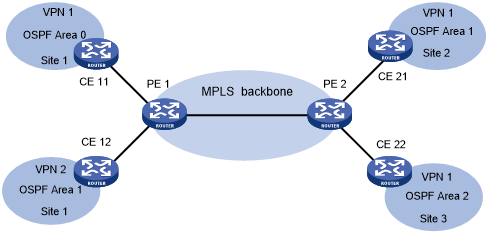
As shown in Figure 58, CE 11, CE 21, and CE 22 belong to the same VPN and the same OSPF domain.
Before domain ID configuration, VPN 1 routes are advertised from CE 11 to CE 21 and CE 22 by using the following process:
PE 1 redistributes OSPF routes from CE 11 into BGP, and advertises the VPN routes to PE 2 through BGP.
PE 2 redistributes the BGP routes to OSPF, and advertises them to CE 21 and CE 22 in AS External LSAs (Type 5) or NSSA External LSAs (Type 7).
After domain ID configuration, VPN 1 routes are advertised from CE 11 to CE 21 and CE 22 by using the following process:
PE 1 redistributes OSPF routes into BGP, adds the domain ID to the redistributed BGP VPNv4 routes as a BGP extended community attribute, and advertises the routes to PE 2.
PE 2 compares the domain ID in the received routes with the locally configured domain ID. If they are the same and the received routes are intra-area or inter-area routes, OSPF advertises these routes in Network Summary LSAs (Type 3). Otherwise, OSPF advertises these routes in AS External LSAs (Type 5) or NSSA External LSAs (Type 7).
Routing loop avoidance
Figure 59: Network diagram for routing loop avoidance
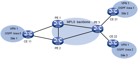
As shown in Figure 59, Site 1 is connected to two PEs. When a PE advertises VPN routes learned from MP-BGP to Site 1 through OSPF, the routes might be received by the other PE. This results in a routing loop.
OSPF VPN extension uses the following tags to avoid routing loops:
DN bit (for Type 3 LSAs)—When a PE redistributes BGP routes into OSPF and creates Type 3 LSAs, it sets the DN bit for the LSAs. When receiving the Type 3 LSAs advertised by CE 11, the other PE ignores the LSAs whose DN bit is set to avoid routing loops.
Route tag (for Type 5 or 7 LSAs)—The two PEs use the same route tag. When a PE redistributes BGP routes into OSPF and creates Type 5 or 7 LSAs, it adds the route tag to the LSAs. When receiving the Type 5 or 7 LSAs advertised by CE 11, the other PE compares the route tag in the LSAs against the local route tag. If they are the same, the PE ignores the LSAs to avoid routing loops.
OSPF sham link
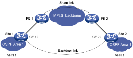
As shown in Figure 60, two routes exist between Site 1 and Site 2 of VPN 1:
A route over MPLS backbone—It is an inter-area route if PE 1 and PE 2 have the same domain ID, or is an external route if PE 1 and PE 2 are configured with no domain ID or with different domain IDs.
A direct route between CEs—It is an intra-area route that is called a backdoor link.
VPN traffic is always forwarded through the backdoor link because it has a higher priority than the inter-area route. To forward VPN traffic over the inter-area route, you can establish a sham link between the two PEs to change the inter-area route to an intra-area route.
Figure 60: Network diagram for sham link
A sham link is considered a virtual point-to-point link within a VPN and is advertised in a Type 1 LSA. It is identified by the source IP address and destination IP address that are the local PE address and the remote PE address in the VPN address space. Typically, the source and destination addresses are loopback interface addresses with a 32-bit mask.
To add a route to the destination IP address of a sham link to a VPN instance, the remote PE must advertise the source IP address of the sham link as a VPN-IPv4 address through MP-BGP. To avoid routing loops, a PE does not advertise the sham link's destination address.