Nested VPN
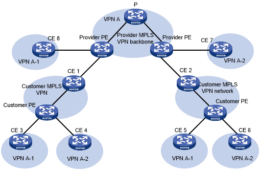
The nested VPN technology exchanges VPNv4 routes between PEs and CEs of the ISP MPLS L3VPN and allows a customer to manage its own internal VPNs. Figure 55 shows a nested VPN network. On the service provider's MPLS VPN network, there is a customer VPN named VPN A. The customer VPN contains two sub-VPNs, VPN A-1 and VPN A-2.
The service provider PEs consider the customer's network as a common VPN user and do not join any sub-VPNs. The service provider CE devices (CE 1 and CE 2) exchange VPNv4 routes including sub-VPN routing information with the service provider PEs, which implements the propagation of the sub-VPN routing information throughout the customer network.
The nested VPN technology supports both symmetric networking and asymmetric networking. Sites of the same VPN can have the same number or different numbers of internal VPNs. Nested VPN also supports multiple-level nesting of internal VPNs.
Figure 55: Network diagram for nested VPN
Propagation of routing information
In a nested VPN network, routing information is propagated by using the following process:
After receiving VPN routes from customer CEs, a customer PE advertises VPN-IPv4 routes to the provider CEs through MP-BGP.
The provider CEs advertise the VPN-IPv4 routes to a provider PE through MP-BGP.
After receiving a VPN-IPv4 route, the provider PE keeps the customer's internal VPN information, and appends the customer's MPLS VPN attributes on the service provider network. It replaces the RD of the VPN-IPv4 route with the RD of the customer's MPLS VPN on the service provider network. It also adds the export route-target (ERT) attribute of the customer's MPLS VPN on the service provider network to the extended community attribute list of the route. The internal VPN information for the customer is maintained on the provider PE.
The provider PE advertises VPN-IPv4 routes carrying the comprehensive VPN information to the other PEs of the service provider.
After another provider PE receives the VPN-IPv4 routes, it matches the VPN-IPv4 routes to the import targets of its local VPNs. Each local VPN accepts routes of its own and advertises them to provider CEs. If a provider CE (such as CE 7 and CE 8 in Figure 55) is connected to a provider PE through an IPv4 connection, the PE advertises IPv4 routes to the CE. If it is a VPN-IPv4 connection (a customer MPLS VPN network), the PE advertises VPN-IPv4 routes to the CE.
After receiving VPN-IPv4 routes from the provider CE, a customer PE matches those routes to local import targets. Each customer VPN accepts only its own routes and advertises them to connected customer CEs (such as CE 3, CE 4, CE 5, and CE 6 in Figure 55).