RSVP GR configuration example
Network requirements
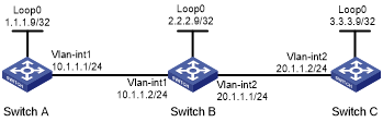
Switch A, Switch B, and Switch C run IS-IS, and all of them are Layer 2 switches.
Use RSVP-TE to establish a TE tunnel from Switch A to Switch C.
Configure RSVP GR on the switches to ensure continuous forwarding when a switch reboots.
Figure 41: Network diagram
Configuration procedure
Configure IP addresses and masks for interfaces. (Details not shown.)
Configure IS-IS to advertise interface addresses, including the loopback interface address. (Details not shown.)
Configure an LSR ID, enable MPLS, MPLS TE, RSVP, and RSVP hello extension:
# Configure Switch A.
<SwitchA> system-view
[SwitchA] mpls lsr-id 1.1.1.9
[SwitchA] mpls te
[SwitchA-te] quit
[SwitchA] rsvp
[SwitchA-rsvp] quit
[SwitchA] interface vlan-interface 1
[SwitchA-Vlan-interface1] mpls enable
[SwitchA-Vlan-interface1] mpls te enable
[SwitchA-Vlan-interface1] rsvp enable
[SwitchA-Vlan-interface1] rsvp hello enable
[SwitchA-Vlan-interface1] quit
# Configure Switch B.
<SwitchB> system-view
[SwitchB] mpls lsr-id 2.2.2.9
[SwitchB] mpls te
[SwitchB-te] quit
[SwitchB] rsvp
[SwitchB-rsvp] quit
[SwitchB-mpls] interface vlan-interface 1
[SwitchB-Vlan-interface1] mpls enable
[SwitchB-Vlan-interface1] mpls te enable
[SwitchB-Vlan-interface1] rsvp enable
[SwitchB-Vlan-interface1] rsvp hello enable
[SwitchB-Vlan-interface1] quit
[SwitchB] interface vlan-interface 2
[SwitchB-Vlan-interface2] mpls enable
[SwitchB-Vlan-interface2] mpls te enable
[SwitchB-Vlan-interface2] rsvp enable
[SwitchB-Vlan-interface2] rsvp hello enable
[SwitchB-Vlan-interface2] quit
# Configure Switch C.
<SwitchC> system-view
[SwitchC] mpls lsr-id 3.3.3.9
[SwitchC] mpls te
[SwitchC-te] quit
[SwitchC] rsvp
[SwitchC-rsvp] quit
[SwitchC] interface vlan-interface 2
[SwitchC-Vlan-interface2] mpls enable
[SwitchC-Vlan-interface2] mpls te enable
[SwitchC-Vlan-interface2] rsvp enable
[SwitchC-Vlan-interface2] rsvp hello enable
[SwitchC-Vlan-interface2] quit
Configure IS-IS TE. (Details not shown.)
Configure an MPLS TE tunnel. (Details not shown.)
Configure RSVP GR:
# Configure Switch A.
[SwitchA] rsvp
[SwitchA-rsvp] graceful-restart enable
# Configure Switch B.
[SwitchB] rsvp
[SwitchB-rsvp] graceful-restart enable
# Configure Switch C.
[SwitchC] rsvp
[SwitchC-rsvp] graceful-restart enable
Verifying the configuration
# After a tunnel is established from Switch A and Switch C, display detailed RSVP neighbor information on Switch A.
<SwitchA> display rsvp peer verbose
Peer: 10.1.1.2                            Interface: Vlan1
Hello state: Up                           Hello type: Active
P2P PSB count: 0                          P2P RSB count: 1
P2MP PSB count: 0                         P2MP RSB count: 0
Src instance: 0x1f08                      Dst instance: 0x22
Summary refresh: Disabled                 Graceful Restart state: Ready
Peer GR restart time: 120000 ms           Peer GR recovery time: 0 ms
The output shows that the neighbor's GR state is Ready.