Configuring TTL propagation
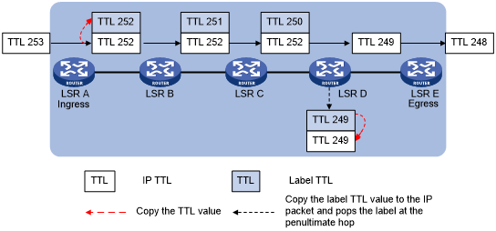
When TTL propagation is enabled, the ingress node copies the TTL value of an IP packet to the TTL field of the label. Each LSR on the LSP decreases the label TTL value by 1. The LSR that pops the label copies the remaining label TTL value back to the IP TTL of the packet. The IP TTL value can reflect how many hops the packet has traversed in the MPLS network. The IP tracert facility can show the real path along which the packet has traveled.
Figure 6: TTL propagation
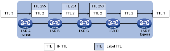
When TTL propagation is disabled, the ingress node sets the label TTL to 255. Each LSR on the LSP decreases the label TTL value by 1. The LSR that pops the label does not change the IP TTL value when popping the label. Therefore, the MPLS backbone nodes are invisible to user networks, and the IP tracert facility cannot show the real path in the MPLS network.
Figure 7: Without TTL propagation
Follow these guidelines when you configure TTL propagation:
As a best practice, set the same TTL processing mode on all LSRs of an LSP.
To enable TTL propagation for a VPN, you must enable it on all PE devices in the VPN. Then, you can get the same traceroute result (hop count) from those PEs.
After TTL propagation is enabled or disabled, execute the reset mpls ldp command to make the configuration take effect.
After TTL propagation is disabled, the device cannot perform correct DSCP-to-EXP mapping for IP packets entering the MPLS network.
To enable TTL propagation:
Step | Command | Remarks |
|---|---|---|
1. Enter system view. | system-view | N/A |
2. Enable TTL propagation. | mpls ttl propagate { public | vpn } | By default, TTL propagation is enabled for public network packets and is disabled for VPN packets. This command affects only the propagation between IP TTL and label TTL. Within an MPLS network, TTL is always copied between the labels of an MPLS packet. |