Auto-mode MFF configuration example in a tree network
Network requirements
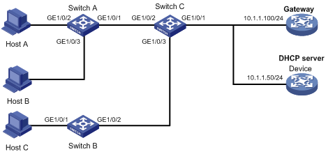
As shown in Figure 153, all the devices are in VLAN 100. Hosts A, B, and C obtain IP addresses from the DHCP server.
Configure MFF to isolate the hosts at Layer 2 and allow them to communicate with each other through the gateway at Layer 3.
Figure 152: Network diagram
Configuration procedure
Configure the IP addresses of the gateway and the DHCP server, as shown in Figure 153.
Configure Switch A:
# Enable DHCP snooping.
<SwitchA> system-view
[SwitchA] dhcp snooping enable
# Enable MFF in automatic mode on VLAN 100.
[SwitchA] vlan 100
[SwitchA-vlan100] mac-forced-forwarding auto
[SwitchA-vlan100] quit
# Configure IP address 10.1.1.50 for the DHCP server.
[SwitchA-vlan100] mac-forced-forwarding server 10.1.1.50
# Configure GigabitEthernet 1/0/1 as a network port.
[SwitchA] interface gigabitethernet 1/0/1
[SwitchA-GigabitEthernet1/0/1] mac-forced-forwarding network-port
# Configure GigabitEthernet 1/0/1 as a DHCP snooping trusted port.
[SwitchA-GigabitEthernet1/0/1] dhcp snooping trust
Configure Switch B:
# Enable DHCP snooping.
<SwitchB> system-view
[SwitchB] dhcp snooping enable
# Enable MFF in automatic mode on VLAN 100.
[SwitchB] vlan 100
[SwitchB-vlan100] mac-forced-forwarding auto
[SwitchB-vlan100] quit
# Configure IP address 10.1.1.50 for the DHCP server.
[SwitchB-vlan100] mac-forced-forwarding server 10.1.1.50
# Configure GigabitEthernet 1/0/2 as a network port.
[SwitchB] interface gigabitethernet 1/0/2
[SwitchB-GigabitEthernet1/0/2] mac-forced-forwarding network-port
# Configure GigabitEthernet 1/0/2 as a DHCP snooping trusted port.
[SwitchB-GigabitEthernet1/0/2] dhcp snooping trust