AAA for 802.1X users by a RADIUS server
Network requirements
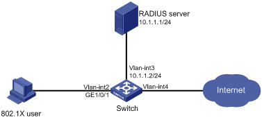
As shown in Figure 23, configure the switch to meet the following requirements:
Use the RADIUS server for authentication, authorization, and accounting of 802.1X users.
Use MAC-based access control on GigabitEthernet 1/0/1 to authenticate all 802.1X users on the port separately.
Include domain names in the usernames sent to the RADIUS server.
On the RADIUS server, perform the following tasks:
Add a service that assigns authenticated users to VLAN 4.
Configure a user account named dot1x@bbb and assign the service to the user.
Set the shared keys to expert for secure RADIUS communication. Set the ports for authentication and accounting to 1812 and 1813, respectively.
Figure 22: Network diagram
Configuration procedure
Configure interfaces and VLANs, so the host promptly obtains a new IP address to access resources in the authorized VLAN after passing authentication. (Details not shown.)
If you are using IMC PLAT 5.0, configure the RADIUS server as follows:
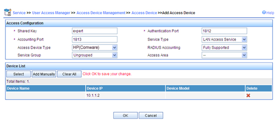
# Add the switch to the IMC Platform as an access device.
Log in to IMC, click the Service tab, and select User Access Manager > Access Device Management > Access Device from the navigation tree. Then, click Add to configure an access device as follows:
Set the shared key for secure authentication and accounting communication to expert.
Set the ports for authentication and accounting to 1812 and 1813, respectively.
Select LAN Access Service from the Service Type list.
Select HP(Comware) from the Access Device Type list.
Select the access device from the device list or manually add the device with IP address 10.1.1.2.
Use the default values for other parameters and click OK.
The IP address of the access device specified here must be the same as the source IP address of the RADIUS packets sent from the switch. The source IP address is chosen in the following order on the switch:
IP address specified by the nas-ip command.
IP address specified by the radius nas-ip command.
IP address of the outbound interface (the default).
Figure 23: Adding the switch as an access device
![[NOTE: ]](images/note.png) | NOTE: In this section, IMC UAM 5.0 (E0101) is used as the authentication and accounting RADIUS server. IMC UAM 5.0 (E0101) is running on IMC PLAT 5.0 (E0101). | |
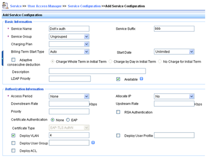
# Add a service.
Click the Service tab, and select User Access Manager > Service Configuration from the navigation tree. Then, click Add to configure a service as follows:
Add a service named Dot1x auth, and set the service suffix to bbb, the authentication domain for the 802.1X user. With the service suffix configured, you must configure the access device to send usernames that include domain names to the RADIUS server.
Select Deploy VLAN and set the ID of the VLAN to be assigned to 4.
Configure other parameters as needed.
Click OK.
Figure 24: Adding a service
# Add a user.
Click the User tab, and select Access User View > All Access Users from the navigation tree to enter the All Access Users page. Then, click Add to configure a user as follows:
Select the user or add a user named hello.
Specify the account name as dot1x and configure the password.
Select Dot1x auth in the Access Service area.
Configure other parameters as needed and click OK.
Figure 25: Adding an access user account

Configure the switch:
Configure a RADIUS scheme:
# Create a RADIUS scheme named rad and enter RADIUS scheme view.
<Switch> system-view
[Switch] radius scheme rad
# Specify the primary authentication server and primary accounting server, and configure the keys for communication with the servers.
[Switch-radius-rad] primary authentication 10.1.1.1
[Switch-radius-rad] primary accounting 10.1.1.1
[Switch-radius-rad] key authentication simple expert
[Switch-radius-rad] key accounting simple expert
# Include domain names in the usernames sent to the RADIUS server.
[Switch-radius-rad] user-name-format with-domain
[Switch-radius-rad] quit
Configure an authentication domain:
# Create an ISP domain named bbb and enter ISP domain view.
[Switch] domain bbb
# Configure the ISP domain to use RADIUS scheme rad for authentication, authorization, and accounting of LAN users.
[Switch-isp-bbb] authentication lan-access radius-scheme rad
[Switch-isp-bbb] authorization lan-access radius-scheme rad
[Switch-isp-bbb] accounting lan-access radius-scheme rad
[Switch-isp-bbb] quit
Configure 802.1X authentication:
# Enable 802.1X globally.
[Switch] dot1x
# Enable 802.1X for GigabitEthernet 1/0/1.
[Switch] interface gigabitethernet 1/0/1
[Switch-GigabitEthernet1/0/1] dot1x
[Switch-GigabitEthernet1/0/1] quit
# Configure the access control method. By default, an 802.1X-enabled port uses the MAC-based access control.
[Switch] dot1x port-method macbased interface gigabitethernet 1/0/1
Verifying the configuration
On the host, use account dot1x@bbb to pass 802.1X authentication:
# If the host runs the Windows XP 802.1X client, configure the network connection properties as follows:
Click the Authentication tab of the properties window.
Select the Enable IEEE 802.1X authentication for this network option.
Select MD5 challenge as the EAP type.
Click OK.
The user passes authentication after entering the correct username and password on the authentication page.
# If the host runs the iNode client, no advanced authentication options are required. The user can pass authentication after entering username dot1x@bbb and the correct password on the client property page.
On the switch, verify that the server assigns the port connecting the client to VLAN 4 after the user passes authentication. (Details not shown.)
Display 802.1X connection information on the switch.
[Switch] display dot1x connection