Configuration example for QinQ termination supporting DHCP relay
Network requirements
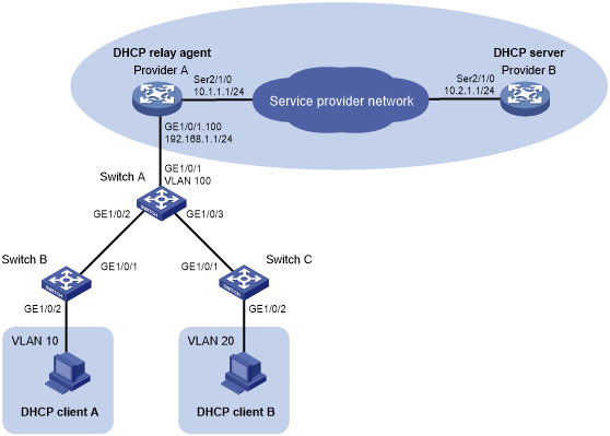
As shown in Figure 9:
Provider A and Provider B are edge devices on the service provider network.
DHCP client A and DHCP client B are devices on the customer networks.
Provider A is the DHCP relay agent. Provider B is the DHCP server.
Provider A and Provider B communicate with each other through Layer 3 interfaces.
Configure QinQ termination on Provider A so that DHCP client A and DHCP client B can obtain IP settings from Provider B.
Figure 9: Network diagram
Configuration procedure
Configure the DHCP relay agent Provider A:
# Enable DHCP service.
<ProviderA> system-view
[ProviderA] dhcp enable
# Create a Layer 3 Ethernet subinterface GigabitEthernet 1/0/1.100.
[ProviderA] interface gigabitethernet 1/0/1.100
# Configure GigabitEthernet 1/0/1.100 to terminate packets whose Layer 1 ID is 100 and Layer 2 VLAN ID is 10 or 20.
[ProviderA-GigabitEthernet1/0/1.100] vlan-type dot1q vid 100 second-dot1q 10 20
# Enable GigabitEthernet 1/0/1.100 to transmit broadcast and multicast packets.
[ProviderA-GigabitEthernet1/0/1.100] vlan-termination broadcast enable
# Enable DHCP relay on GigabitEthernet 1/0/1.100 and specify 10.2.1.1 as the DHCP server address.
[ProviderA-GigabitEthernet1/0/1.100] dhcp select relay
[ProviderA-GigabitEthernet1/0/1.100] dhcp relay server-address 10.2.1.1
# Assign an IP address to GigabitEthernet 1/0/1.100.
[ProviderA-GigabitEthernet1/0/1.100] ip address 192.168.1.1 24
[ProviderA-GigabitEthernet1/0/1.100] quit
# Enable recording of relay entries on the relay agent.
[ProviderA] dhcp relay client-information record
# Assign an IP address to the interface Serial 2/1/0.
[ProviderA] interface serial 2/1/0
[ProviderA-Serial2/1/0] ip address 10.1.1.1 24
[ProviderA-Serial2/1/0] quit
# Configure a static route to the DHCP server.
[ProviderA] ip route-static 10.2.1.1 24 10.1.1.1
Configure the DHCP server Provider B:
# Assign an IP address to the DHCP server.
<ProviderB> system-view
[ProviderB] interface serial 2/1/0
[ProviderB-Serial2/1/0] ip address 10.2.1.1 24
[ProviderB-Serial2/1/0] quit
# Enable DHCP.
[ProviderB] dhcp enable
# Configure an IP address pool on the DHCP server.
[ProviderB] dhcp server ip-pool 1
[ProviderB-dhcp-pool-1] network 192.168.1.0 24
[ProviderB-dhcp-pool-1] gateway-list 192.168.1.1
[ProviderB-dhcp-pool-1] quit
# Configure a static route to GigabitEthernet 1/0/1.100.
[ProviderB] ip route-static 192.168.1.1 24 10.1.1.1
Configure Switch A:
# Configure the uplink port GigabitEthernet 1/0/1 as a trunk port, and assign the port to VLAN 100.
<SwitchA> system-view
[SwitchA] interface gigabitethernet 1/0/1
[SwitchA-GigabitEthernet1/0/1] port link-type trunk
[SwitchA-GigabitEthernet1/0/1] port trunk permit vlan 100
[SwitchA-GigabitEthernet1/0/1] quit
# Configure the downlink port GigabitEthernet 1/0/2 as a trunk port, and assign the port to VLANs 10 and 100.
[SwitchA] interface gigabitethernet 1/0/2
[SwitchA-GigabitEthernet1/0/2] port link-type trunk
[SwitchA-GigabitEthernet1/0/2] port trunk permit vlan 10 100
# Set the PVID of GigabitEthernet 1/0/2 to VLAN 100.
[SwitchA-GigabitEthernet1/0/2] port trunk pvid vlan 100
# Enable QinQ on GigabitEthernet1/0/2.
[SwitchA-GigabitEthernet1/0/2] qinq enable
[SwitchA-GigabitEthernet1/0/2] quit
# Configure the downlink port GigabitEthernet 1/0/3 as a trunk port, and assign the port to VLANs 20 and 100.
[SwitchA] interface gigabitethernet 1/0/3
[SwitchA-GigabitEthernet1/0/3] port link-type trunk
[SwitchA-GigabitEthernet1/0/3] port trunk permit vlan 20 100
# Set the PVID of GigabitEthernet 1/0/3 to VLAN 100.
[SwitchA-GigabitEthernet1/0/3] port trunk pvid vlan 100
# Enable QinQ on GigabitEthernet 1/0/3.
[SwitchA-GigabitEthernet1/0/3] qinq enable
[SwitchA-GigabitEthernet1/0/3] quit
# Assign GigabitEthernet 1/0/2 and GigabitEthernet 1/0/3 to VLAN 100.
[SwitchA] vlan 100
[SwitchA-vlan100] port gigabitethernet 1/0/2
[SwitchA-vlan100] port gigabitethernet 1/0/3
Configure Switch B:
# Create VLAN 10.
<SwitchB> system-view
[SwitchB] vlan 10
# Assign GigabitEthernet 1/0/2 to VLAN 10.
[SwitchB-vlan10] port gigabitethernet 1/0/2
[SwitchB-vlan10] quit
# Configure GigabitEthernet 1/0/1 as a trunk port, and assign the port to VLAN 10.
[SwitchB] interface gigabitethernet 1/0/1
[SwitchB-GigabitEthernet1/0/1] port link-type trunk
[SwitchB-GigabitEthernet1/0/1] port trunk permit vlan 10
Configure Switch C:
# Create VLAN 20.
<SwitchC> system-view
[SwitchC] vlan 20
# Assign GigabitEthernet 1/0/2 to VLAN 20.
[SwitchC-vlan20] port gigabitethernet 1/0/2
[SwitchC-vlan20] quit
# Configure GigabitEthernet 1/0/1 as a trunk port, and assign the port to VLAN 20.
[SwitchC] interface gigabitethernet 1/0/1
[SwitchC-GigabitEthernet1/0/1] port link-type trunk
[SwitchC-GigabitEthernet1/0/1] port trunk permit vlan 20
Verifying the configuration
# Verify that DHCP client A and DHCP client B can obtain IP settings from Provider B. (Details not shown.)