Ambiguous QinQ termination configuration example
Network requirements
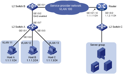
As shown in Figure 7, QinQ is enabled on GigabitEthernet 1/0/2 of Layer 2 Switch B.
Configure ambiguous QinQ termination, so that hosts can communicate with the server group.
Figure 7: Network diagram
Configuration procedure
In this example, Layer 2 Switch C uses the factory configuration.
Configure Host A, Host B, and Host C:
# Assign IP addresses 1.1.1.1/24, 1.1.1.2/24, and 1.1.1.3/24 to Host A, Host B, and Host C, respectively. (Details not shown.)
# Specify 1.1.1.11/24 as the gateway address for the hosts. (Details not shown.)
Configure Layer 2 Switch A:
# Create VLAN 11.
<L2_SwitchA> system-view
[L2_SwitchA] vlan 11
# Assign GigabitEthernet 1/0/1 to VLAN 11.
[L2_SwitchA-vlan11] port gigabitethernet 1/0/1
[L2_SwitchA-vlan11] quit
# Create VLAN 12.
[L2_SwitchA] vlan 12
# Assign GigabitEthernet 1/0/2 to VLAN 12.
[L2_SwitchA-vlan12] port gigabitethernet 1/0/2
[L2_SwitchA-vlan12] quit
# Create VLAN 13.
[L2_SwitchA] vlan 13
# Assign GigabitEthernet 1/0/3 to VLAN 13.
[L2_SwitchA-vlan13] port gigabitethernet 1/0/3
[L2_SwitchA-vlan13] quit
# Configure GigabitEthernet 1/0/7 as a trunk port, and assign the port to VLANs 11 through 13.
[L2_SwitchA] interface gigabitethernet 1/0/7
[L2_SwitchA-GigabitEthernet1/0/7] port link-type trunk
[L2_SwitchA-GigabitEthernet1/0/7] port trunk permit vlan 11 to 13
Configure Layer 2 Switch B:
# Configure GigabitEthernet 1/0/2 as a trunk port, and assign the port to VLANs 11 through 13 and VLAN 100.
<L2_SwitchB> system-view
[L2_SwitchB] interface gigabitethernet 1/0/2
[L2_SwitchB-GigabitEthernet1/0/2] port link-type trunk
[L2_SwitchB-GigabitEthernet1/0/2] port trunk permit vlan 11 to 13 100
# Set the PVID of GigabitEthernet 1/0/2 to VLAN 100.
[L2_SwitchB-GigabitEthernet1/0/2] port trunk pvid vlan 100
# Enable QinQ on GigabitEthernet 1/0/2.
[L2_SwitchB-GigabitEthernet1/0/2] qinq enable
[L2_SwitchB-GigabitEthernet1/0/2] quit
# Configure GigabitEthernet 1/0/1 as a trunk port, and assign the port to VLAN 100.
[L2_SwitchB] interface gigabitethernet 1/0/1
[L2_SwitchB-GigabitEthernet1/0/1] port link-type trunk
[L2_SwitchB-GigabitEthernet1/0/1] port trunk permit vlan 100
Configure the router:
# Create Ethernet subinterface GigabitEthernet 1/0/1.10, and assign an IP address to the subinterface.
<Router> system-view
[Router] interface gigabitethernet 1/0/1.10
[Router-GigabitEthernet1/0/1.10] ip address 1.1.1.11 255.255.255.0
# Configure GigabitEthernet 1/0/1.10 to terminate VLAN-tagged packets whose Layer 1 VLAN ID is 100 and Layer 2 VLAN ID is 11, 12, or 13.
[Router-GigabitEthernet1/0/1.10] vlan-type dot1q vid 100 second-dot1q 11 to 13
# Enable GigabitEthernet 1/0/1.10 to transmit broadcasts and multicasts.
[Router-GigabitEthernet1/0/1.10] vlan-termination broadcast enable
[Router-GigabitEthernet1/0/1.10] quit
# Assign an IP address to GigabitEthernet 1/0/2.
[Router] interface gigabitethernet 1/0/2
[Router-GigabitEthernet1/0/2] ip address 1.1.2.11 255.255.255.0
Configure the server group:
# Assign each device in the server group an IP address on the network segment 1.1.2.0/24. (Details not shown.)
# Specify 1.1.2.11/24 as the gateway IP address for the server group. (Details not shown.)
Verifying the configuration
# Verify that Host A, Host B, and Host C can ping the server group. (Details not shown.)