Unambiguous Dot1q termination configuration example
Network requirements
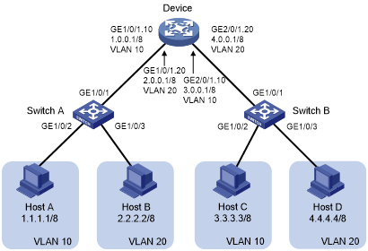
As shown in Figure 3, configure unambiguous Dot1q termination on subinterfaces of the device to implement intra-VLAN and inter-VLAN communications between hosts.
Figure 3: Network diagram
Configuration procedure
Configure Host A, Host B, Host C, and Host D:
# On Host A, specify 1.1.1.1/8 and 1.0.0.1/8 as its IP address and gateway IP address, respectively. (Details not shown.)
# On Host B, specify 2.2.2.2/8 and 2.0.0.1/8 as its IP address and gateway IP address, respectively. (Details not shown.)
# On Host C, specify 3.3.3.3/8 and 3.0.0.1/8 as its IP address and gateway IP address, respectively. (Details not shown.)
# On Host D, specify 4.4.4.4/8 and 4.0.0.1/8 as its IP address and gateway IP address, respectively. (Details not shown.)
Configure Layer 2 Switch A:
# Create VLAN 10.
<L2_SwitchA> system-view
[L2_SwitchA] vlan 10
# Assign GigabitEthernet 1/0/2 to VLAN 10.
[L2_SwitchA-vlan10] port gigabitethernet 1/0/2
[L2_SwitchA-vlan10] quit
# Create VLAN 20.
[L2_SwitchA] vlan 20
# Assign GigabitEthernet 1/0/3 to VLAN 20.
[L2_SwitchA-vlan20] port gigabitethernet 1/0/3
[L2_SwitchA-vlan20] quit
# Configure GigabitEthernet 1/0/1 as a trunk port, and assign the port to VLANs 10 and 20.
[L2_SwitchA] interface gigabitethernet 1/0/1
[L2_SwitchA-GigabitEthernet1/0/1] port link-type trunk
[L2_SwitchA-GigabitEthernet1/0/1] port trunk permit vlan 10 20
Configure Layer 2 Switch B in the same way you configure Layer 2 Switch A. (Details not shown.)
Configure the device:
# Create GigabitEthernet 1/0/1.10, and assign an IP address to this interface.
<Device> system-view
[Device] interface gigabitethernet 1/0/1.10
[Device-GigabitEthernet1/0/1.10] ip address 1.0.0.1 255.0.0.0
# Configure GigabitEthernet 1/0/1.10 to terminate packets tagged with VLAN 10.
[Device-GigabitEthernet1/0/1.10] vlan-type dot1q vid 10
[Device-GigabitEthernet1/0/1.10] quit
# Create GigabitEthernet 1/0/1.20, and assign an IP address to this interface.
[Device] interface gigabitethernet 1/0/1.20
[Device-GigabitEthernet1/0/1.20] ip address 2.0.0.1 255.0.0.0
# Configure GigabitEthernet 1/0/1.20 to terminate packets tagged with VLAN 20.
[Device-GigabitEthernet1/0/1.20] vlan-type dot1q vid 20
[Device-GigabitEthernet1/0/1.20] quit
# Configure GigabitEthernet 2/0/1.10, and assign an IP address to this interface.
[Device] interface gigabitethernet 2/0/1.10
[Device-GigabitEthernet2/0/1.10] ip address 3.0.0.1 255.0.0.0
# Configure GigabitEthernet 2/0/1.10 to terminate packets tagged with VLAN 10.
[Device-GigabitEthernet2/0/1.10] vlan-type dot1q vid 10
[Device-GigabitEthernet2/0/1.10] quit
# Configure GigabitEthernet 2/0/1.20, and assign an IP address to this interface.
[Device] interface gigabitethernet 2/0/1.20
[Device-GigabitEthernet2/0/1.20] ip address 4.0.0.1 255.0.0.0
# Configure GigabitEthernet 2/0/1.20 to terminate packets tagged with VLAN 20.
[Device-GigabitEthernet2/0/1.20] vlan-type dot1q vid 20
[Device-GigabitEthernet2/0/1.20] quit
Verifying the configuration
# Verify that Host A, Host B, Host C, and Host D can ping each other. (Details not shown.)