Working mechanism
Figure 52: Network diagram
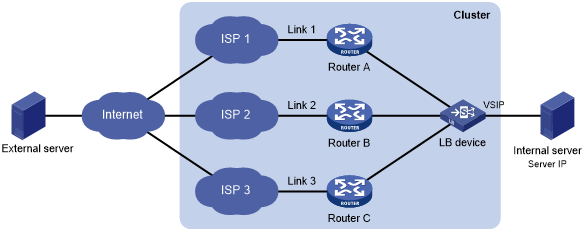
As shown in Figure 52, outbound link load balancing contains the following elements:
Cluster—Provides services. A cluster contains an LB device and multiple ISP links.
LB device—Distributes outbound traffic among multiple links.
Link—Physical links provided by ISPs.
VSIP—Virtual service IP address of the cluster, which identifies the destination network for packets from the internal network.
Server IP—IP address of an internal server.
Figure 53 shows the outbound link load balancing workflow.
Figure 53: Outbound link load balancing workflow
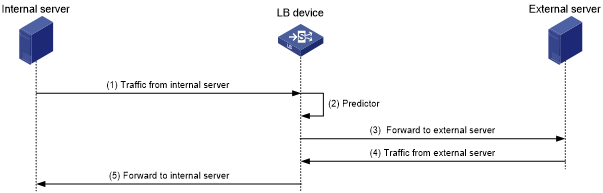
The workflow for outbound link load balancing is as follows:
The LB device receives traffic from the internal server.
The LB device selects the optimal link based on the LB policy, sticky method, proximity algorithm, and scheduling algorithm (typically the bandwidth algorithm or maximum bandwidth algorithm) in turn.
The LB device forwards the traffic to the external server through the optimal link.
The LB device receives traffic from the external server.
The LB device forwards the traffic to the internal server.