Redundancy group members
Member interfaces
Member interfaces of a redundancy group are on the IRF member devices bound to the group's nodes. The member interfaces are assigned to the redundancy group nodes. Member interfaces on one node back up the member interfaces on the other node.
The state of member interfaces depends on the state of the redundancy group nodes:
When the high-priority node is in primary state, member interfaces are up on both the high-priority and the low-priority nodes.
When the high-priority node is in secondary state, the Reth module shuts down the member interfaces on the high-priority node. Member interfaces on the low-priority node are up.
As shown in Figure 31, member interfaces GigabitEthernet 1/0/1 and GigabitEthernet 1/0/2 are on Node 1. Member interfaces GigabitEthernet 2/0/1 and GigabitEthernet 2/0/2 are on Node 2. Dynamic routing protocols are configured on the IP networks to ensure that traffic is forwarded by Device A. When Node 1 with priority 20 acts as the primary node, all member interfaces on Node 1 and Node 2 are up.
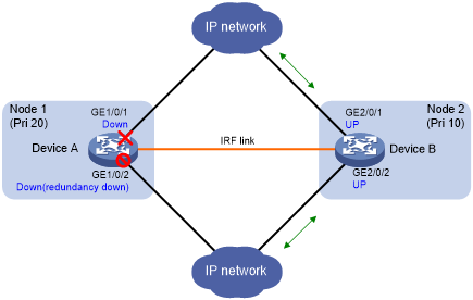
When GigabitEthernet 1/0/1 fails, the redundancy group switches over to Node 2, as shown in Figure 32. GigabitEthernet 1/0/2 is shut down by the Reth module. GigabitEthernet 2/0/1 and GigabitEthernet 2/0/2 are up so that traffic is forwarded by Node 2.
Figure 31: States of member interfaces when both nodes operate correctly (in IRF mode)
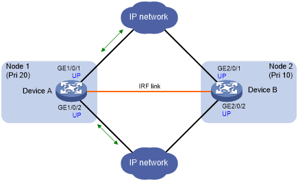
Figure 32: States of member interfaces after a switchover (in IRF mode)
Reth interfaces
A Reth interface in a redundancy group has the following characteristics:
Each IRF member device hosts one member interface of the Reth interface.
The high-priority member of the Reth interface belongs to the high-priority node.
The state of the Reth interface's members depends on the state of the redundancy group nodes.
When the high-priority node is in primary state, the high-priority member is active.
When the low-priority node is in primary state, the low-priority member is active.
As shown inFigure 30, Reth 1 and Reth 2 are in redundancy group 1. GigabitEthernet 1/0/1 and GigabitEthernet 2/0/1 are members of Reth 1, and GigabitEthernet 1/0/2 and GigabitEthernet 2/0/2 are members of Reth 2. Table 7 shows that the members on Node 1 are active because the node is in primary state.
Table 7: Reth interfaces in redundancy group 1
Redundancy group nodes | Members of Reth 1 | Members of Reth 2 |
|---|---|---|
Node 1 (primary) Priority: 20 | GigabitEthernet 1/0/1 (active) Priority: 20 | GigabitEthernet 1/0/2 (active) Priority: 20 |
Node 2 (secondary) Priority: 10 | GigabitEthernet 2/0/1 (inactive) Priority: 10 | GigabitEthernet 2/0/2 (inactive) Priority: 10 |
When GigabitEthernet 1/0/1 of Reth 1 fails, the redundancy group switches over to Node 2. As shown inTable 8, the members on Node 2 are active because the node is in primary state.
Table 8: Reth interfaces in redundancy group 1 after a switchover
Redundancy group nodes | Members of Reth 1 | Members of Reth 2 |
|---|---|---|
Node 1 (secondary) Priority: 20 | GigabitEthernet 1/0/1 (inactive) Priority: 20 | GigabitEthernet 1/0/2 (inactive) Priority: 20 |
Node 2 (primary) Priority: 10 | GigabitEthernet 2/0/1 (active) Priority: 10 | GigabitEthernet 2/0/2 (active) Priority: 10 |