IPsec implementation
To implement IPsec protection for packets between two peers, complete the following tasks on each peer:
Configure an IPsec policy, which defines the range of packets to be protected by IPsec and the security parameters used for the protection.
Apply the IPsec policy to an interface or an application.
When you apply an IPsec policy to an interface, you implement IPsec based on the interface. Packets received and sent by the interface are protected according to the IPsec policy. When you apply an IPsec policy to an application, you implement IPsec based on the application. Packets of the application are protected according to the IPsec policy, regardless of the receiving and sending interface of the packets.
IPsec protects packets as follows:
When an IPsec peer identifies the packets to be protected according to the IPsec policy, it sets up an IPsec tunnel and sends the packet to the remote peer through the tunnel. The IPsec tunnel can be manually configured beforehand, or it can be set up through IKE negotiation triggered by the packet. The IPsec tunnels are actually the IPsec SAs. The inbound packets are protected by the inbound SA, and the outbound packets are protected by the outbound SA.
When the remote IPsec peer receives the packet, it drops, de-encapsulates, or directly forwards the packet according to the configured IPsec policy.
Interface-based IPsec can be further divided into ACL-based IPsec and tunnel interface-based IPsec.
ACL-based IPsec
To implement ACL-based IPsec, configure an ACL to define the data flows to be protected, specify the ACL in an IPsec policy, and then apply the IPsec policy to an interface. When packets sent by the interface match a permit rule of the ACL, the packets are protected by the outbound IPsec SA and encapsulated with IPsec. When the interface receives an IPsec packet destined for the local device, it searches for the inbound IPsec SA according to the SPI in the IPsec packet header for de-encapsulation. If the de-encapsulated packet matches a permit rule of the ACL, the device processes the packet. If the de-encapsulated packet does not match any permit rule of the ACL, the device drops the packet.
The device supports the following data flow protection modes:
Standard mode—One IPsec tunnel protects one data flow. The data flow permitted by an ACL rule is protected by one IPsec tunnel that is established solely for it.
Aggregation mode—One IPsec tunnel protects all data flows permitted by all the rules of an ACL. This mode is only used to communicate with old-version devices.
Per-host mode—One IPsec tunnel protects one host-to-host data flow. One host-to-host data flow is identified by one ACL rule and protected by one IPsec tunnel established solely for it. This mode consumes more system resources when multiple data flows exist between two subnets to be protected.
Tunnel interface-based IPsec
To implement tunnel interface-based IPsec, configure an IPsec profile and apply the IPsec profile to a tunnel interface. All traffic, including multicast traffic, routed to the tunnel interface is protected by IPsec. Tunnel interface-based IPsec only supports the tunnel encapsulation mode.
In the current software version, tunnel interface-based IPsec is supported only on ADVPN and IPsec tunnel interfaces.
Tunnel interface-based IPsec has the following advantages:
Simplifies configuration. Tunnel interface-based IPsec protects all traffic routed to the tunnel interface. It does not require an ACL to identify traffic to be protected. The simplicity of the tunnel interface-based IPsec configuration makes it adaptable to network changes and expansions, which reduces the network maintenance costs.
Reduces costs. IPsec tunnel interface-based IPsec simplifies encapsulation and reduces bandwidth costs, compared with IPsec over GRE or IPsec over L2TP, which requires additional GRE or L2TP encapsulation.
Facilitates service application. Tunnel interface-based IPsec has a clear division of the before encapsulation phase and the after encapsulation phase. You can apply other services, for example, NAT or QoS in a proper phase according to the network requirements. For example, to use QoS before IPsec encapsulation, apply a QoS policy to the tunnel interface. To use QoS after encapsulation, apply a QoS policy to the physical output interface.
Figure 122: Tunnel interface encapsulation
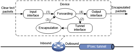
As shown in Figure 127, a tunnel interface encapsulates an IP packet as follows:
Upon receiving a clear text packet, the input interface sends the packet to the forwarding module.
The forwarding module looks up the route table and sends the packet to the tunnel interface.
The tunnel interface encapsulates the packet into a new IP packet. The source and destination IP addresses in the new IP header are the source and destination IP addresses of the tunnel interface. After encapsulation, the tunnel interface sends the packet to the forwarding module.
The forwarding module looks up the route table again and sends the packet out of the physical interface of the tunnel interface.
Figure 123: Tunnel interface de-encapsulation
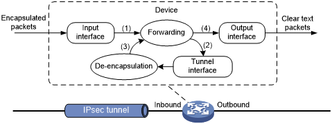
As shown in Figure 128, a tunnel interface de-encapsulates an IP packet as follows:
Upon receiving an encapsulated packet, the inbound interface sends the packet to the forwarding module.
Because the packet is destined for the source IP address of the tunnel interface and the payload protocol is AH or ESP, the forwarding module sends the packet to the tunnel interface.
The tunnel interface de-encapsulates the packet (removes the outer IP header) and sends the de-encapsulated packet back to the forwarding module.
The forwarding module looks up the routing table again and sends the packet out of the output interface.
Application-based IPsec
Application-based IPsec does not require an ACL. You can implement application-based IPsec by binding an IPsec profile to an application protocol. All packets of the application protocol are encapsulated with IPsec. This method can be used to protect IPv6 routing protocols. The supported IPv6 routing protocols include OSPFv3, IPv6 BGP, and RIPng.
All packets of the applications that are not bound to IPsec and the IPsec packets that failed to be de-encapsulated are dropped.
In one-to-many communication scenarios, you must configure the IPsec SAs for an IPv6 routing protocol in manual mode because of the following reasons:
The automatic key exchange mechanism is used only to protect communications between two points. In one-to-many communication scenarios, automatic key exchange cannot be implemented.
One-to-many communication scenarios require that all the devices use the same SA parameters (SPI and key) to receive and send packets. IKE negotiated SAs cannot meet this requirement.