Configuring direct portal authentication
Network requirements
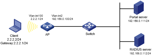
As shown in Figure 87, the AP directly forwards user traffic from the client. The client is assigned a public IP address either manually or through DHCP. A portal server acts as both a portal authentication server and a portal Web server. A RADIUS server acts as the authentication/accounting server.
Configure direct portal authentication, so the client can access only the portal Web server before passing the authentication and access other network resources after passing the authentication.
Figure 80: Network diagram
Configuration prerequisites
Configure IP addresses for the client, AP, switch, and servers as shown in Figure 87 and make sure they can reach each other.
Configure the RADIUS server correctly to provide authentication and accounting functions.
Configuring the portal server on IMC PLAT 5.0
In this example, the portal server runs on IMC PLAT 5.0(E0101) and IMC UAM 5.0(E0101).
Configure the portal authentication server:
Log in to IMC and click the Service tab.
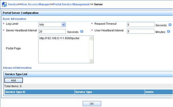
Select User Access Manager > Portal Service Management > Server from the navigation tree to open the portal server configuration page, as shown in Figure 88.
Configure the portal server parameters as needed.
This example uses the default settings.
Click OK.
Figure 81: Portal server configuration
Configure the IP address group:
Select User Access Manager > Portal Service Management > IP Group from the navigation tree to open the portal IP address group configuration page.
Click Add to open the page as shown in Figure 89.
Figure 82: Adding an IP address group
Enter the start IP address and end IP address of the IP group.
Make sure the host IP address is in the IP group.
Select a service group.
This example uses the default group Ungrouped.
Select the action Normal.
Click OK.
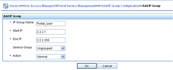
Enter the IP group name.
Enter the start IP address and end IP address of the IP group.
Make sure the host IP address is in the IP group.
Select a service group.
This example uses the default group Ungrouped.
Select the action Normal.
Click OK.
Add a portal device:
Select User Access Manager > Portal Service Management > Device from the navigation tree to open the portal device configuration page.
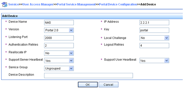
Click Add to open the page as shown in Figure 90.
Enter the device name NAS.
Enter the IP address of the router's interface connected to the client.
Enter the key, which must be the same as that configured on the router.
Set whether to enable IP address reallocation.
This example uses direct portal authentication, and therefore select No from the Reallocate IP list.
Select whether to support sever heartbeat and user heartbeat functions.
In this example, select No for both Support Server Heartbeat and Support User Heartbeat.
Click OK.
Figure 83: Adding a portal device
Associate the portal device with the IP address group:
As shown in Figure 91, click the icon in the Port Group Information Management column of device NAS to open the port group configuration page.
Figure 84: Device list
Select the configured IP address group.
The IP address used by the user to access the network must be within this IP address group.
Use the default settings for other parameters.
Click OK.

Click Add to open the page as shown in Figure 92.
Figure 85: Adding a port group
Select the configured IP address group.
The IP address used by the user to access the network must be within this IP address group.
Use the default settings for other parameters.
Click OK.
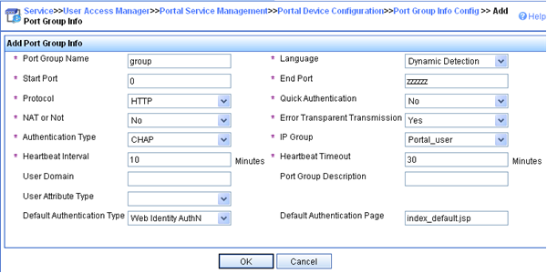
Enter the port group name.
Select the configured IP address group.
The IP address used by the user to access the network must be within this IP address group.
Use the default settings for other parameters.
Click OK.
Configuring the portal authentication server on IMC PLAT 7.1
In this example, the portal server runs on IMC PLAT 7.1(E0303) and IMC EIA 7.1(F0303).
Configure the portal authentication server:
Log in to IMC and click the User tab.
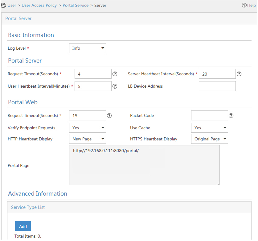
Select User Access Policy > Portal Service > Server from the navigation tree to open the portal server configuration page, as shown in Figure 93.
Configure the portal server parameters as needed.
This example uses the default settings.
Click OK.
Figure 86: Portal authentication server configuration
Configure the IP address group:
Select User Access Policy > Portal Service > IP Group from the navigation tree to open the portal IP address group configuration page.
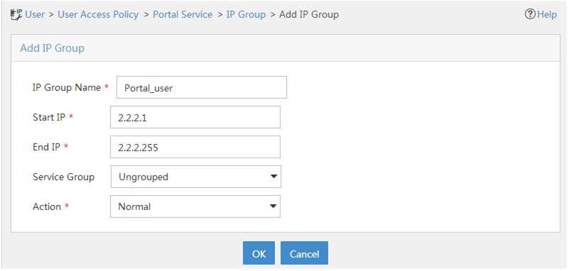
Click Add to open the page as shown in Figure 94.
Enter the IP group name.
Enter the start IP address and end IP address of the IP group.
Make sure the client IP address (2.2.2.2) is in the IP group.
Select a service group.
This example uses the default group Ungrouped.
Select Normal from the Action list.
Click OK.
Figure 87: Adding an IP address group
Add a portal device:
Select User Access Policy > Portal Service > Device from the navigation tree to open the portal device configuration page.
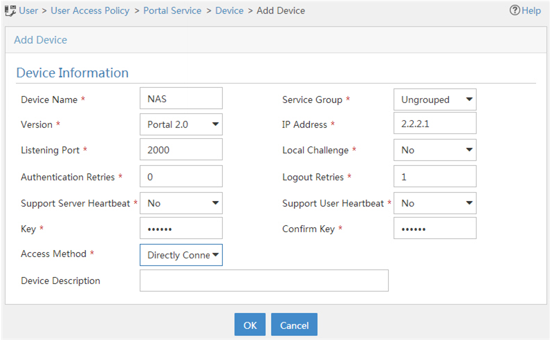
Click Add to open the page as shown inFigure 95
Enter the device name.
Enter the IP address of the router's interface connected to the client.
Enter the key, which must be the same as that configured on the router.
Select Directly Connected for Access Method in this example.
Set whether to support the portal server heartbeat and user heartbeat functions.
In this example, select No for both Support Server Heartbeat and Support User Heartbeat.
Click OK.
Figure 88: Adding a portal device
Associate the portal device with the IP address group:
As shown inFigure 96 click the Port Group Information Management icon for device NAS to open the port group configuration page.
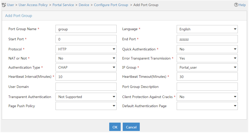
Click Add to open the page as shown inFigure 97
Enter the port group name.
Select the configured IP address group.
The IP address used by the user to access the network must be within this IP address group.
Use the default settings for other parameters.
Click OK.
Figure 89: Device list
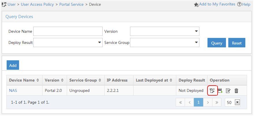
Figure 90: Adding a port group
Configuring the AP
Configure a RADIUS scheme:
# Create a RADIUS scheme named rs1 and enter its view.
<AP> system-view
[AP] radius scheme rs1
# Specify the primary authentication server and primary accounting server, and configure the keys for communication with the servers.
[AP-radius-rs1] primary authentication 192.168.0.112
[AP-radius-rs1] primary accounting 192.168.0.112
[AP-radius-rs1] key authentication simple radius
[AP-radius-rs1] key accounting simple radius
# Exclude the ISP domain name from the username sent to the RADIUS server.
[AP-radius-rs1] user-name-format without-domain
[AP-radius-rs1] quit
# Enable RADIUS session control.
[AP] radius session-control enable
Configure an authentication domain:
# Create an ISP domain named dm1 and enter its view.
[AP] domain dm1
# Configure AAA methods for the ISP domain.
[AP-isp-dm1] authentication portal radius-scheme rs1
[AP-isp-dm1] authorization portal radius-scheme rs1
[AP-isp-dm1] accounting portal radius-scheme rs1
[AP-isp-dm1] quit
# Configure domain dm1 as the default ISP domain. If a user enters the username without the ISP domain name at login, the authentication and accounting methods of the default domain are used for the user.
[AP] domain default enable dm1
Configure portal authentication:
# Configure a portal authentication server.
[AP] portal server newpt
[AP-portal-server-newpt] ip 192.168.0.111 key simple portal
[AP-portal-server-newpt] port 50100
[AP-portal-server-newpt] quit
# Configure a portal Web server.
[AP] portal web-server newpt
[AP-portal-websvr-newpt] url http://192.168.0.111:8080/portal
[AP-portal-websvr-newpt] quit
# Create service template newst, set the SSID to portal 1.
[AP] wlan service-template newst
[AP–wlan-st-newst] ssid portal_1
# Enable direct authentication on service template newst.
[AP–wlan-st-newst] portal enable method direct
# Specify portal Web server newpt on service template newst.
[AP–wlan-st-newst] portal apply web-server newpt
# Configure the BAS-IP as 2.2.2.1 for portal packets sent from the router to the portal authentication server.
[AP–wlan-st-newst] portal bas-ip 2.2.2.1
# Enable service template newst.
[AP–wlan-st-newst] service-template enable
[AP–wlan-st-newst] quit
# Set the working channel to channel 11 for radio 2 of the AP.
[AP] wlan ap ap2
[AP-wlan-ap-ap2] radio 2
[AP-wlan-ap-ap2-radio-2] channel 11
# Enable radio 2 and bind service template newst and VLAN 2 to radio 2.
[AP-wlan-ap-ap2-radio-2] radio enable
[AP-wlan-ap-ap2-radio-2] service-template newst vlan 2
[AP-wlan-ap-ap2-radio-2] quit
[AP-wlan-ap-ap2] quit