Configuration example for connecting a LAN to the Internet through an ADSL modem
Network requirements
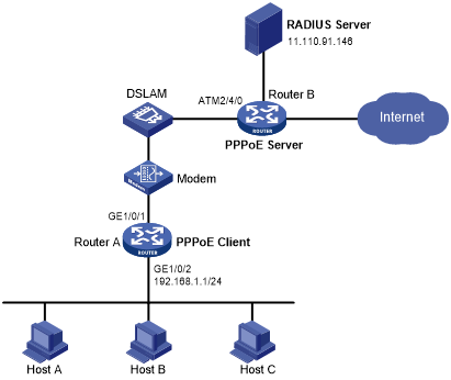
As shown in Figure 19:
Router A provides Internet access for Host A, Host B, and Host C. It connects to the DSLAM through an ADSL modem and a permanent PPPoE session.
The username and password of the ADSL account are user1 and 123456.
Router A operates as a PPPoE client, and it allows the hosts in the LAN to access the Internet without PPPoE client software.
Router B operates as the PPPoE server. It performs RADIUS authentication and accounting.
Figure 19: Network diagram
Configuration procedure
Configure Router A as a PPPoE client:
# Create dialer access group 1 and configure a dial access control rule for it.
<RouterA> system-view
[RouterA] dialer-group 1 rule ip permit
# Enable bundle DDR on Dialer 1.
[RouterA] interface dialer 1
[RouterA-Dialer1] dialer bundle enable
# Associate Dialer 1 with dialer access group 1.
[RouterA-Dialer1] dialer-group 1
# Configure Dialer 1 to obtain an IP address through PPP negotiation.
[RouterA-Dialer1] ip address ppp-negotiate
# Configure the PPPoE session to operate in permanent mode.
[RouterA-Dialer1] dialer timer idle 0
# Configure the PAP username and password.
[RouterA-Dialer1] ppp pap local-user user1 password simple 123456
[RouterA-Dialer1] quit
# Configure a PPPoE session.
[RouterA] interface gigabitethernet 1/0/1
[RouterA-GigabitEthernet1/0/1] pppoe-client dial-bundle-number 1
[RouterA-GigabitEthernet1/0/1] quit
# Configure an IP address for the LAN interface.
[RouterA] interface gigabitethernet 1/0/2
[RouterA-GigabitEthernet1/0/2] ip address 192.168.1.1 255.255.255.0
[RouterA-GigabitEthernet1/0/2] quit
# Configure a default route.
[RouterA] ip route-static 0.0.0.0 0 dialer 1
If the hosts in the LAN use private addresses, configure NAT on Router A. For more information about NAT, see Layer 3—IP Services Configuration Guide.
Configure Router B as the PPPoE server:
# Configure Virtual-Template 1 to use PAP for authentication and use a PPP address pool to assign IP addresses.
<RouterB> system-view
[RouterB] interface virtual-template 1
[RouterB-Virtual-Template1] ppp authentication-mode pap domain system
[RouterB-Virtual-Template1] remote address pool 1
[RouterB-Virtual-Template1] ip address 1.1.1.1 255.0.0.0
[RouterB-Virtual-Template1] quit
# Configure a local PPP address pool that contains nine assignable IP addresses.
[RouterB] ip pool 1 1.1.1.2 1.1.1.10
# Enable the PPPoE server on the Virtual-Ethernet 1.
[RouterB] interface virtual-ethernet 1
[RouterB-Virtual-Ethernet1] mac-address 0001-0000-0001
[RouterB-Virtual-Ethernet1] pppoe-server bind virtual-template 1
[RouterB-Virtual-Ethernet1] quit
# Configure an ATM interface.
[RouterB] interface atm 2/4/0.1
[RouterB-ATM2/4/0.1] pvc to_adsl_a 0/60
[RouterB-ATM2/4/0.1-pvc-to_adsl_a-0/60] map bridge virtual-ethernet 1
[RouterB-ATM2/4/0.1-pvc-to_adsl_a-0/60] quit
[RouterB-Atm2/4/0.1] quit
# Configure the default ISP domain (system) to use the RADIUS scheme for authentication, authorization, and accounting.
[RouterB] domain system
[RouterB-isp-system] authentication ppp radius-scheme cams
[RouterB-isp-system] authorization ppp radius-scheme cams
[RouterB-isp-system] accounting ppp radius-scheme cams
[RouterB-isp-system] quit
# Configure a RADIUS scheme, and assign an IP address and port number for the RADIUS server.
[RouterB] radius scheme cams
[RouterB-radius-cams] primary authentication 11.110.91.146 1812
[RouterB-radius-cams] primary accounting 11.110.91.146 1813
# Set the shared keys for secure communication with the RADIUS server to expert in plain text.
[RouterB-radius-cams] key authentication simple expert
[RouterB-radius-cams] key accounting simple expert
[RouterB-radius-cams] quit
Configure the RADIUS server:
# Configure the authentication and accounting passwords as expert.
# Add a PPPoE user with username user1 and password 123456.
For more information about RADIUS, see Security Configuration Guide.
Verifying the configuration
# Display summary information for the PPPoE session between Router A and Router B.
[RouterA] display pppoe-client session summary
Bundle ID    Interface    VA          RemoteMAC      LocalMAC       State
1      1     GE1/0/1      VA0         0001-0000-0001 00e0-1500-4100 SESSION
Host A, Host B, and Host C can thus access the Internet. For example, they can browse a web page through IE.