MSTP configuration example
Network requirements
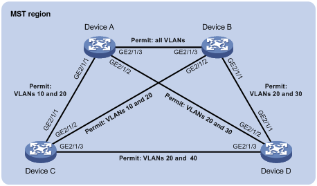
As shown in Figure 45, all devices on the network are in the same MST region. Device A and Device B work at the distribution layer. Device C and Device D work at the access layer.
Configure MSTP so that frames of different VLANs are forwarded along different spanning trees.
VLAN 10 frames are forwarded along MSTI 1.
VLAN 30 frames are forwarded along MSTI 3.
VLAN 40 frames are forwarded along MSTI 4.
VLAN 20 frames are forwarded along MSTI 0.
VLAN 10 and VLAN 30 are terminated on the distribution layer devices, and VLAN 40 is terminated on the access layer devices. The root bridges of MSTI 1 and MSTI 3 are Device A and Device B, respectively, and the root bridge of MSTI 4 is Device C.
Figure 45: Network diagram
Configuration procedure
Configure VLANs and VLAN member ports. (Details not shown.)
Create VLAN 10, VLAN 20, and VLAN 30 on both Device A and Device B.
Create VLAN 10, VLAN 20, and VLAN 40 on Device C.
Create VLAN 20, VLAN 30, and VLAN 40 on Device D.
Configure the ports on these devices as trunk ports and assign them to related VLANs.
Configure Device A:
# Enter MST region view, and configure the MST region name as example.
<DeviceA> system-view
[DeviceA] stp region-configuration
[DeviceA-mst-region] region-name example
# Map VLAN 10, VLAN 30, and VLAN 40 to MSTI 1, MSTI 3, and MSTI 4, respectively.
[DeviceA-mst-region] instance 1 vlan 10
[DeviceA-mst-region] instance 3 vlan 30
[DeviceA-mst-region] instance 4 vlan 40
# Configure the revision level of the MST region as 0.
[DeviceA-mst-region] revision-level 0
# Activate MST region configuration.
[DeviceA-mst-region] active region-configuration
[DeviceA-mst-region] quit
# Configure the current device as the root bridge of MSTI 1.
[DeviceA] stp instance 1 root primary
# Enable the spanning tree feature globally.
[DeviceA] stp global enable
Configure Device B:
# Enter MST region view, and configure the MST region name as example.
<DeviceB> system-view
[DeviceB] stp region-configuration
[DeviceB-mst-region] region-name example
# Map VLAN 10, VLAN 30, and VLAN 40 to MSTI 1, MSTI 3, and MSTI 4, respectively.
[DeviceB-mst-region] instance 1 vlan 10
[DeviceB-mst-region] instance 3 vlan 30
[DeviceB-mst-region] instance 4 vlan 40
# Configure the revision level of the MST region as 0.
[DeviceB-mst-region] revision-level 0
# Activate MST region configuration.
[DeviceB-mst-region] active region-configuration
[DeviceB-mst-region] quit
# Configure the current device as the root bridge of MSTI 3.
[DeviceB] stp instance 3 root primary
# Enable the spanning tree feature globally.
[DeviceB] stp global enable
Configure Device C:
# Enter MST region view, and configure the MST region name as example.
<DeviceC> system-view
[DeviceC] stp region-configuration
[DeviceC-mst-region] region-name example
# Map VLAN 10, VLAN 30, and VLAN 40 to MSTI 1, MSTI 3, and MSTI 4, respectively.
[DeviceC-mst-region] instance 1 vlan 10
[DeviceC-mst-region] instance 3 vlan 30
[DeviceC-mst-region] instance 4 vlan 40
# Configure the revision level of the MST region as 0.
[DeviceC-mst-region] revision-level 0
# Activate MST region configuration.
[DeviceC-mst-region] active region-configuration
[DeviceC-mst-region] quit
# Configure the current device as the root bridge of MSTI 4.
[DeviceC] stp instance 4 root primary
# Enable the spanning tree feature globally.
[DeviceC] stp global enable
Configure Device D:
# Enter MST region view, and configure the MST region name as example.
<DeviceD> system-view
[DeviceD] stp region-configuration
[DeviceD-mst-region] region-name example
# Map VLAN 10, VLAN 30, and VLAN 40 to MSTI 1, MSTI 3, and MSTI 4, respectively.
[DeviceD-mst-region] instance 1 vlan 10
[DeviceD-mst-region] instance 3 vlan 30
[DeviceD-mst-region] instance 4 vlan 40
# Configure the revision level of the MST region as 0.
[DeviceD-mst-region] revision-level 0
# Activate MST region configuration.
[DeviceD-mst-region] active region-configuration
[DeviceD-mst-region] quit
# Enable the spanning tree feature globally.
[DeviceD] stp global enable
Verifying the configuration
In this example, Device B has the lowest root bridge ID. As a result, Device B is elected as the root bridge in MSTI 0.
When the network is stable, you can use the display stp brief command to display brief spanning tree information on each device.
# Display brief spanning tree information on Device A.
[DeviceA] display stp brief
[DeviceA] display stp brief
 MST ID      Port                         Role  STP State     Protection
 0           GigabitEthernet2/1/1         ALTE  DISCARDING    NONE
 0           GigabitEthernet2/1/2         DESI  FORWARDING    NONE
 0           GigabitEthernet2/1/3         ROOT  FORWARDING    NONE
 1           GigabitEthernet2/1/1         DESI  FORWARDING    NONE
 1           GigabitEthernet2/1/3         DESI  FORWARDING    NONE
 3           GigabitEthernet2/1/2         DESI  FORWARDING    NONE
 3           GigabitEthernet2/1/3         ROOT  FORWARDING    NONE
# Display brief spanning tree information on Device B.
[DeviceB] display stp brief
 MST ID      Port                         Role  STP State     Protection
 0           GigabitEthernet2/1/1         DESI  FORWARDING    NONE
 0           GigabitEthernet2/1/2         DESI  FORWARDING    NONE
 0           GigabitEthernet2/1/3         DESI  FORWARDING    NONE
 1           GigabitEthernet2/1/2         DESI  FORWARDING    NONE
 1           GigabitEthernet2/1/3         ROOT  FORWARDING    NONE
 3           GigabitEthernet2/1/1         DESI  FORWARDING    NONE
 3           GigabitEthernet2/1/3         DESI  FORWARDING    NONE
# Display brief spanning tree information on Device C.
[DeviceC] display stp brief
 MST ID      Port                         Role  STP State     Protection
 0           GigabitEthernet2/1/1         DESI  FORWARDING    NONE
 0           GigabitEthernet2/1/2         ROOT  FORWARDING    NONE
 0           GigabitEthernet2/1/3         DESI  FORWARDING    NONE
 1           GigabitEthernet2/1/1         ROOT  FORWARDING    NONE
 1           GigabitEthernet2/1/2         ALTE  DISCARDING    NONE
 4           GigabitEthernet2/1/3         DESI  FORWARDING    NONE
# Display brief spanning tree information on Device D.
[DeviceD] display stp brief
 MST ID      Port                         Role  STP State     Protection
 0           GigabitEthernet2/1/1         ROOT  FORWARDING    NONE
 0           GigabitEthernet2/1/2         ALTE  DISCARDING    NONE
 0           GigabitEthernet2/1/3         ALTE  DISCARDING    NONE
 3           GigabitEthernet2/1/1         ROOT  FORWARDING    NONE
 3           GigabitEthernet2/1/2         ALTE  DISCARDING    NONE
 4           GigabitEthernet2/1/3         ROOT  FORWARDING    NONE
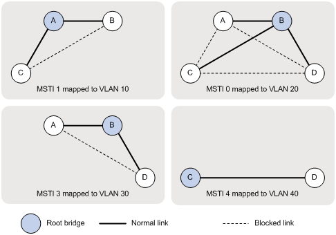
Based on the output, you can draw each MSTI mapped to each VLAN, as shown in Figure 46.
Figure 46: MSTIs mapped to different VLANs