MSTP basic concepts
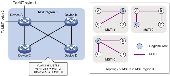
Figure 33 shows a switched network that contains four MST regions, each MST region containing four MSTP devices. Figure 34 shows the networking topology of MST region 3.
Figure 33: Basic concepts in MSTP
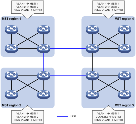
Figure 34: Network diagram and topology of MST region 3
MST region
A multiple spanning tree region (MST region) consists of multiple devices in a switched network and the network segments among them. All these devices have the following characteristics:
A spanning tree protocol enabled
Same region name
Same VLAN-to-instance mapping configuration
Same MSTP revision level
Physically linked together
Multiple MST regions can exist in a switched network. You can assign multiple devices to the same MST region, as shown in Figure 33.
The switched network contains four MST regions, MST region 1 through MST region 4.
All devices in each MST region have the same MST region configuration.
MSTI
MSTP can generate multiple independent spanning trees in an MST region, and each spanning tree is mapped to the specific VLANs. Each spanning tree is referred to as a multiple spanning tree instance (MSTI).
In Figure 34, MST region 3 contains three MSTIs, MSTI 1, MSTI 2, and MSTI 0.
VLAN-to-instance mapping table
As an attribute of an MST region, the VLAN-to-instance mapping table describes the mapping relationships between VLANs and MSTIs.
In Figure 34, the VLAN-to-instance mapping table of MST region 3 is as follows:
VLAN 1 to MSTI 1.
VLAN 2 and VLAN 3 to MSTI 2.
Other VLANs to MSTI 0.
MSTP achieves load balancing by means of the VLAN-to-instance mapping table.
CST
The common spanning tree (CST) is a single spanning tree that connects all MST regions in a switched network. If you regard each MST region as a device, the CST is a spanning tree calculated by these devices through STP or RSTP.
The blue lines in Figure 33 represent the CST.
IST
An internal spanning tree (IST) is a spanning tree that runs in an MST region. It is also called MSTI 0, a special MSTI to which all VLANs are mapped by default.
In Figure 33, MSTI 0 is the IST in MST region 3.
CIST
The common and internal spanning tree (CIST) is a single spanning tree that connects all devices in a switched network. It consists of the ISTs in all MST regions and the CST.
In Figure 33, the ISTs (MSTI 0) in all MST regions plus the inter-region CST constitute the CIST of the entire network.
Regional root
The root bridge of the IST or an MSTI within an MST region is the regional root of the IST or MSTI. Based on the topology, different spanning trees in an MST region might have different regional roots, as shown in MST region 3 in Figure 34.
The regional root of MSTI 1 is Device B.
The regional root of MSTI 2 is Device C.
The regional root of MSTI 0 (also known as the IST) is Device A.
Common root bridge
The common root bridge is the root bridge of the CIST.
In Figure 33, the common root bridge is a device in MST region 1.
Port roles
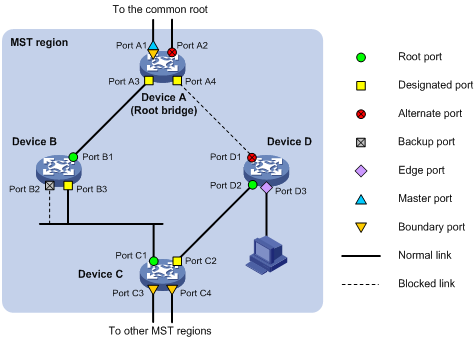
A port can play different roles in different MSTIs. As shown in Figure 35, an MST region contains Device A, Device B, Device C, and Device D. Port A1 and port A2 of Device A connect to the common root bridge. Port B2 and Port B3 of Device B form a loop. Port C3 and Port C4 of Device C connect to other MST regions. Port D3 of Device D directly connects to a host.
Figure 35: Port roles
MSTP calculation involves the following port roles:
Root port—Forwards data for a non-root bridge to the root bridge. The root bridge does not have any root port.
Designated port—Forwards data to the downstream network segment or device.
Alternate port—Acts as the backup port for a root port or master port. When the root port or master port is blocked, the alternate port takes over.
Backup port—Acts as the backup port of a designated port. When the designated port is invalid, the backup port becomes the new designated port. A loop occurs when two ports of the same spanning tree device are connected, so the device blocks one of the ports. The blocked port acts as the backup.
Edge port—Directly connects to a user host rather than a network device or network segment.
Master port—Acts as a port on the shortest path from the local MST region to the common root bridge. The master port is not always located on the regional root. It is a root port on the IST or CIST and still a master port on the other MSTIs.
Boundary port—Connects an MST region to another MST region or to an STP/RSTP-running device. In MSTP calculation, a boundary port's role on an MSTI is consistent with its role on the CIST. However, that is not true with master ports. A master port on MSTIs is a root port on the CIST.
Port states
In MSTP, a port can be in one of the following states:
Forwarding—The port receives and sends BPDUs, learns MAC addresses, and forwards user traffic.
Learning—The port receives and sends BPDUs, learns MAC addresses, but does not forward user traffic. Learning is an intermediate port state.
Discarding—The port receives and sends BPDUs, but does not learn MAC addresses or forward user traffic.
![[NOTE: ]](images/note.png) | NOTE: When in different MSTIs, a port can be in different states. | |
A port state is not exclusively associated with a port role. Table 11 lists the port states that each port role supports. (A check mark [√] indicates that the port supports this state, while a dash [—] indicates that the port does not support this state.)
Table 11: Port states that different port roles support
Port role (right) Port state (below) | Root port/master port | Designated port | Alternate port | Backup port |
|---|---|---|---|---|
Forwarding | √ | √ | — | — |
Learning | √ | √ | — | — |
Discarding | √ | √ | √ | √ |