Layer 3 aggregation load sharing configuration example
Network requirements
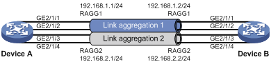
On the network shown in Figure 12, perform the following tasks:
Configure Layer 3 static aggregation groups 1 and 2 on Device A and Device B, respectively.
Configure IP addresses and subnet masks for the corresponding Layer 3 aggregate interfaces.
Configure link aggregation group 1 to load share packets based on source IP addresses.
Configure link aggregation group 2 to load share packets based on destination IP addresses.
Figure 12: Network diagram
Configuration procedure
Configure Device A:
# Create Layer 3 aggregate interface Route-Aggregation 1.
<DeviceA> system-view
[DeviceA] interface route-aggregation 1
# Configure Layer 3 aggregation group 1 to load share packets based on source IP addresses.
[DeviceA-Route-Aggregation1] link-aggregation load-sharing mode source-ip
# Configure an IP address and subnet mask for Layer 3 aggregate interface Route-Aggregation 1.
[DeviceA-Route-Aggregation1] ip address 192.168.1.1 24
[DeviceA-Route-Aggregation1] quit
# Assign Layer 3 Ethernet interfaces GigabitEthernet 2/1/1 and GigabitEthernet 2/1/2 to aggregation group 1.
[DeviceA] interface gigabitethernet 2/1/1
[DeviceA-GigabitEthernet2/1/1] port link-aggregation group 1
[DeviceA-GigabitEthernet2/1/1] quit
[DeviceA] interface gigabitethernet 2/1/2
[DeviceA-GigabitEthernet2/1/2] port link-aggregation group 1
[DeviceA-GigabitEthernet2/1/2] quit
# Create Layer 3 aggregate interface Route-Aggregation 2.
[DeviceA] interface route-aggregation 2
# Configure Layer 3 aggregation group 2 to load share packets based on destination IP addresses.
[DeviceA-Route-Aggregation2] link-aggregation load-sharing mode destination-ip
# Configure an IP address and subnet mask for Layer 3 aggregate interface Route-Aggregation 2.
[DeviceA-Route-Aggregation2] ip address 192.168.2.1 24
[DeviceA-Route-Aggregation2] quit
# Assign Layer 3 Ethernet interfaces GigabitEthernet 2/1/3 and GigabitEthernet 2/1/4 to aggregation group 2.
[DeviceA] interface gigabitethernet 2/1/3
[DeviceA-GigabitEthernet2/1/3] port link-aggregation group 2
[DeviceA-GigabitEthernet2/1/3] quit
[DeviceA] interface gigabitethernet 2/1/4
[DeviceA-GigabitEthernet2/1/4] port link-aggregation group 2
[DeviceA-GigabitEthernet2/1/4] quit
Configure Device B in the same way Device A is configured. (Details not shown.)
Verifying the configuration
# Display detailed information about all aggregation groups on Device A.
[DeviceA] display link-aggregation verbose
Loadsharing Type: Shar -- Loadsharing, NonS -- Non-Loadsharing
Port Status: S -- Selected, U -- Unselected, I -- Individual
Flags:  A -- LACP_Activity, B -- LACP_Timeout, C -- Aggregation,
        D -- Synchronization, E -- Collecting, F -- Distributing,
        G -- Defaulted, H -- Expired

Aggregate Interface: Route-Aggregation1
Aggregation Mode: Static
Loadsharing Type: Shar
  Port             Status  Priority Oper-Key
--------------------------------------------------------------------------------
  GE2/1/1          S       32768    1
  GE2/1/2          S       32768    1

Aggregate Interface: Route-Aggregation2
Aggregation Mode: Static
Loadsharing Type: Shar
  Port             Status  Priority Oper-Key
--------------------------------------------------------------------------------
  GE2/1/3          S       32768    2
  GE2/1/4          S       32768    2
The output shows that:
Link aggregation groups 1 and 2 are both load-shared Layer 3 static aggregation groups.
Each aggregation group contains two Selected ports.
# Display all the group-specific load sharing modes on Device A.
[DeviceA] display link-aggregation load-sharing mode interface

Route-Aggregation1 Load-Sharing Mode:
source-ip address

Route-Aggregation2 Load-Sharing Mode:
destination-ip address
The output shows that:
Link aggregation group 1 load shares packets based on source IP addresses.
Link aggregation group 2 load shares packets based on destination IP addresses.