High-speed CPOS interface configuration example
Network requirements
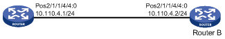
As shown in Figure 7, create 155 Mbps POS channel interfaces for data transmission on the 2.5 Gbps CPOS interfaces between the routers.
Figure 7: Network diagram
Configuration procedure
Configure Router A:
# Set the clock mode to master on the 2.5 Gbps CPOS interface.
<RouterA> system-view
[RouterA] controller cpos 2/1/1
[RouterA-Cpos2/1/1] clock master
# Create a 155 Mbps POS channel interface.
[RouterA-Cpos2/1/1] oc-12 4
[RouterA-Cpos2/1/1-oc-12-4] oc-3 4
[RouterA-Cpos2/1/1-oc-12-4-oc-3-4] using oc-3c
# Assign an IP address to the 155 Mbps POS channel interface.
[RouterA-Cpos2/1/1-oc-12-4-oc-3-4] interface pos 2/1/1/4/4:0
[RouterA-pos2/1/1/4/4:0] ip address 10.110.4.1 255.255.255.0
Configure Router B:
# Create a 155 Mbps POS channel interface.
<RouterB> system-view
[RouterB] controller e-cpos 2/1/1
[RouterB-Cpos2/1/1] oc-12 4
[RouterB-Cpos2/1/1-oc-12-4] oc-3 4
[RouterB-Cpos2/1/1-oc-12-4-oc-3-4] using oc-3c
# Assign an IP address to the 155 Mbps POS channel interface.
[RouterB-Cpos2/1/1-oc-12-4-oc-3-4] interface pos2/1/1/4/4:0
[RouterB-pos2/1/1/4/4:0] ip address 10.110.4.2 255.255.255.0
Verifying the configuration
# Verify that Router A and Router B can ping each other at the POS channel interfaces. (Details not shown.)