CPOS-E1 interface configuration example
Network requirements
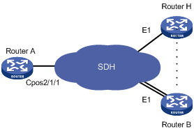
As shown in Figure 6, branch nodes Router B through Router H are uplinked to the central node Router A through E1 links. Router A aggregates these E1 links by using a CPOS interface.
Add one additional E1 link on Router B to expand its capacity, and use an MP-group interface to bind the two E1 links.
Figure 6: Network diagram
Configuration procedure
![[IMPORTANT: ]](images/important.png) | IMPORTANT: For correct network synchronization, make sure the master clock mode is configured on the SONET/SDH devices connected to the routers. | |
Configure Router A:
# Configure E1 channels 1 and 2 of CPOS 2/1/1 to operate in unframed mode.
<RouterA> system-view
[RouterA] controller cpos 2/1/1
[RouterA-Cpos2/1/1] e1 1 unframed
[RouterA-Cpos2/1/1] e1 2 unframed
# Create MP-group 1 and assign an IP address to it.
[RouterA] interface mp-group 2/1/1
[RouterA-Mp-group2/1/1] ip address 10.1.1.1 24
[RouterA-Mp-group2/1/1] quit
# Assign Serial 2/1/1/1:0 to MP-group 2/1/1.
[RouterA] interface serial2/1/1/1:0
[RouterA-Serial2/1/1/1:0] ppp mp mp-group 2/1/1
[RouterA-Serial2/1/1/1:0] quit
# Assign Serial 2/1/1/2:0 to MP-group 2/1/1.
[RouterA] interface serial2/1/1/2:0
[RouterA-Serial2/1/1/2:0] ppp mp mp-group 2/1/1
[RouterA-Serial2/1/1/2:0] quit
Configure Router B:
# Configure E1 2/1/1 to operate in E1 mode.
<RouterB> system-view
[RouterB] controller e1 2/1/1
[RouterB-E1 2/1/1] using e1
[RouterB-E1 2/1/1] quit
# Configure E1 2/1/2 to operate in E1 mode.
[RouterB] controller e1 2/1/2
[RouterB-E1 2/1/2] using e1
[RouterB-E1 2/1/2] quit
# Create MP-group 2/1/1 and assign an IP address to it.
[RouterB] interface mp-group 2/1/1
[RouterB-Mp-group2/1/1] ip address 10.1.1.2 24
[RouterB-Mp-group2/1/1] quit
# Assign Serial 2/1/1:0 to MP-group 2/1/1.
[RouterB] interface serial2/1/1:0
[RouterB-Serial2/1/1:0] ppp mp mp-group 2/1/1
[RouterB-Serial2/1/1:0] quit
# Assign Serial 2/1/2:0 to MP-group 2/1/1.
[RouterB] interface serial2/1/2:0
[RouterB-Serial2/1/2:0] ppp mp mp-group 2/1/1
[RouterB-Serial2/1/2:0] quit
Verifying the configuration
# Verify the serial interface configuration and state, for example, on Router B.
<RouterB> display interface serial 2/1/1:0
# Verify the MP interface, and MP bundle configuration and state, for example, on Router B.
<RouterB> display interface mp-group 2/1/1
<RouterB> display interface display ppp mp
# Verify that the routers can ping one another. (Details not shown.)