Directly connecting routers through POS interfaces
Network requirements
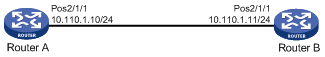
As shown in Figure 2, connect the routers through POS interfaces.
Figure 2: Network diagram
Configuration procedure
Configure POS 2/1/1 on Router A:
# Assign an IP address to the interface.
<RouterA> system-view
[RouterA] interface pos 2/1/1
[RouterA-Pos2/1/1] ip address 10.110.1.10 255.255.255.0
# Configure the data link layer protocol of the interface.
[RouterA-Pos2/1/1] link-protocol ppp
# Set the MTU to 1500 bytes for the interface.
[RouterA-Pos2/1/1] mtu 1500
# Shut down, and then bring up the interface for the settings to take effect.
[RouterA-Pos2/1/1] shutdown
[RouterA-Pos2/1/1] undo shutdown
Configure POS 2/1/1 on Router B:
# Set the clock mode to master on the interface.
<RouterB> system-view
[RouterB] interface pos 2/1/1
[RouterB-Pos2/1/1] clock master
# Assign an IP address to the interface.
[RouterB-Pos2/1/1] ip address 10.110.1.11 255.255.255.0
# Configure the data link layer protocol of the interface.
[RouterB-Pos2/1/1] link-protocol ppp
# Set the MTU to 1500 bytes for the interface.
[RouterB-Pos2/1/1] mtu 1500
# Shut down, and then bring up the interface for the settings to take effect.
[RouterB-Pos2/1/1] shutdown
[RouterB-Pos2/1/1] undo shutdown
Verifying the configuration
# Verify the POS interface settings, for example, on Router A.
<RouterA> display interface pos
# Verify that Router A and Router B can ping each other at the POS interfaces. (Details not shown.)