Cover the connector with a dust cap when it is not connected to any optical fibers.
Connectors connect transceiver modules to the corresponding transmission media. The transceiver modules available for Aruba products use the following types of connectors:
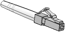
Lucent connector or local connector (LC).
Single LC connectors (also known as Simplex) are typically used for 1G & 10G BiDi (Bidirectional) optics.
Dual LC connectors (Duplex) are typically used in normal optical types.
NOTE:
40G BiDi uses only Duplex fiber versus MPO (see below) for 40G SR4 applications.
Figure 1: LC connector (a simplex connector is shown)
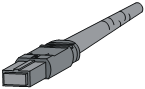
Multifiber Push On (MPO) connector.
Figure 2: MPO connector
The 40G QSFP+ MPO transceiver modules use only female MPO connectors, which have guide holes in the end face of the MPO connector (the transceiver has guide pins within the MPO receptacle).
MPO connectors are classified as the following types based on the polish type:
Physical contact (PC): End face polished flat.
Angle-polished contact (APC): End face polished with an angle, typically 8°.
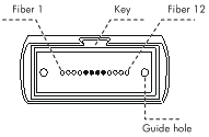
MPO connectors are available with 12 fibers or 24 fibers:
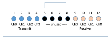
12-fiber MPO connector (40G, SR4, eSR4, and 100G SR4 transceivers use 8 of the available 12 fibers. The four center fibers are unused. )
Figure 3: End face of a 12-fiber connector and channel assignment
MPO transceivers typically use four channels to communicate. These channels are assigned using the outer eight fibers (the center four are unused).
Transmit channels are one set of four fibers, and the receive channels are on the other set of four fibers. Because of this, the cables used and fiber cable connections from endpoint to endpoint effectively create a crossover connection.
Be aware that using two crossover cables in series cancels this effect and no connection will be established. An odd number of crossovers combined with straight-thru fiber connections will effect a crossover connection.
The channel layout indicates that the left four fibers are Transmit, and must reach the opposite transceiver Receive channels (and in proper channel order).
 MPO connectors are classified as the following types based on the polish type: