| Back LED
|
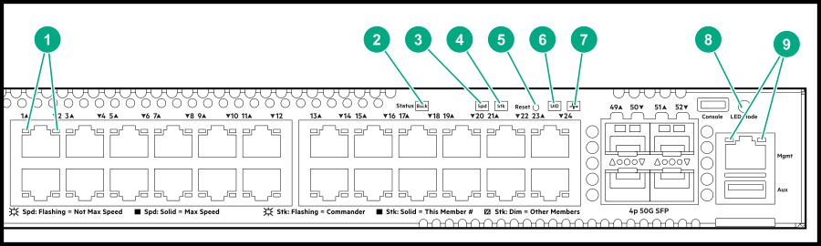
Status of modular components installed in the back of the chassis (not applicable for 6200F/6300F switches
|
On - Green
|
Normal
|
| Slow Flash - Amber
|
Fault in one of the modules in the back of the chassis
|
| PoE LED
|
Indicates Port LEDs are showing PoE information (not applicable for non PoE switches)
|
Off
|
PoE mode not selected
|
| On - Green
|
PoE mode selected
|
| Slow Flash - Amber
|
Hardware failure PoE enabled port, PoE mode not selected
|
| On - Amber
|
Hardware failure PoE enabled port, PoE mode selected
|
| Spd LED
|
Indicates Port LEDs are showing speed information
|
Off
|
Speed mode not selected
|
| On - Green
|
Speed mode selected
|
| Not Implemented
|
No fault defined
|
| Stk LED
|
Indicates Port LEDs are showing stacking mode information
|
Off
|
Stacking mode not selected
|
| On - Green
|
Stacking mode selected
|
| On - Amber
|
A port has a stacking failure. Stacking mode selected
|
| Slow flash Amber
|
A port has a stacking failure. Stacking mode not selected
|
| UID LED
|
User-configurable LED
|
Off
|
User defined the located LED : OFF
|
| On/Flash Blue (for 30 min)
|
User defined the locator LED: On/Flash
|
| Global Status Indicator LED
|
Overall status of the product
|
Flash - Green
|
Self-test in progress during UBOOT, SVOS and ArubaOS-CV
|
| On - Green
|
Successfully initialized ArubaOS-CX
|
| Flash - Amber
|
Recoverable faults (e.g. fans, PSU fault)
|
| On - Amber
|
Critical faults (e.g. exceed temperature limit)
|
| OOBM Status Indicator LED
|
Status of OOBM Link connectivity
|
Off
|
OOBM port is not connected, no link established
|
| Half Bright - Green
|
OOBM port is enabled and established link with partner
|
| On - Green
|
Experiencing high bandwidth utilization
|
| Activity Flicker - Green
|
% of the time that the LED light up is roughly proportional to the % of full bandwidth utilization of the port
|
* Press the Mode Select button to switch between User(default), PoE, Spd, or Stk Mode.
|