Front panel LEDs for 6400 switch series
The Aruba 6400 switches have two management module (MM) slots. Management modules support control plane activities and in-memory running of the Time Series Database.
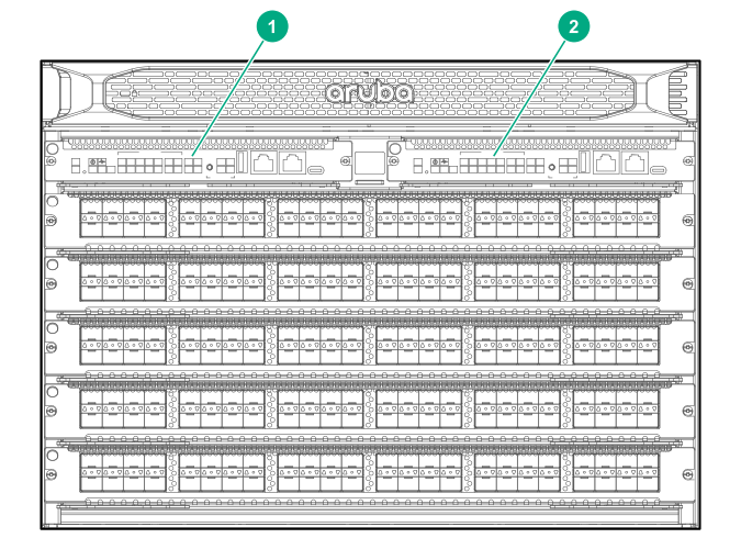
When two management modules are installed, one operates in active mode and the other operates in standby mode. The active slot is determined by election. Installing two management modules provides control plane high availability.
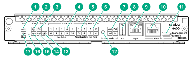
| 1 | Mgmt state (Actv) LED | Indicates the status of the management module after booting. If the MM is the active MM, then the LED glows steady green. |
| 2 | System power LED | When the system is receiving power, glows steady green.=. |
| 3 | Management module health LED (green) | Indicates status of the switch. LED glows steady green when switch is ready after booting from the Network Operating System (NOS). |
| 4 | Line module status LEDs |
Indicates if a line module is installed in a line module slot (1 through 5 for 6405 switches; 1 through 10 on 6410 switches). If a line module is installed in a given slot, then the numbered LED for that slot glows steady green. |
| 5 | Front Power supply status (1 2 3 4) LEDs |
Indicates if a power supply is installed in the slot. If an active power supply is installed, then the LEDs glow steady green. |
| 6 | Fan tray status LEDs (1 - 4) | Indicate if the fan tray is installed in the slot. If a fan tray is installed in the slot, then the LED glows steady green. |
| 7 | LED mode: Usr1, Usr2 Spd, and PoE LEDs |
The display of these LEDs is based on the LED mode button selection.
|
| 8 | Auxillary port | Without a USB device installed, the auxiliary port LED is off after power-on and self-test.
With a USB device installed, this LED displays the following after power-on and self-test:
|
| 9 | Mgmt port (OOBM Port) with Activity/Link LED | Without an active network connection, this LED is off after power-on and self-test completes.
With an active network connection, this LED operates as follows:
|
| 10 | Serial console port (RJ-45) | |
| 11 | USB Micro-B console port | |
| 12 | LED Mode button | Changes the behavior of the line module port LEDs. This button changes the LED behavior from the default Link/Activity behavior to cycle through the PoE, speed (Spd), and user (Usr) options. |
| 13 | UID (Unit Identification) LED | |
| 14 | PoE | Power-over-Ethernet |
| 15 | Chassis temperature status (Temp) LED |
Indicates the status of the chassis temperature. If the temperature is at or below the specified rating, then the LED glows steady green, |
| 16 | Mgmt reset button | A recessed button that is used to reset the selected management module. |
| 17 | Mgmt state (Stby) LED | Indicates the status of the management module after booting. If the MM is the standby MM, then the LED glows steady green. |
Power Supply LEDs
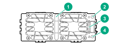
| 1 | Power LED (green) |
| 2 | Power fail LED (amber) |
| 3 | Power supply handle |
| 4 | Latch release tab |
A single PSU is sufficient for fans and management cards to come up and provide user access and diagnostics.
At 220 V AC, only two PSUs are required for full operation and a single PSU is sufficient for the fans and management cards to come up and provide user access/diagnostics.
At 220 V AC: Installing three PSUs offers 2+1 redundancy and installing all four PSUs offers 2+2 redundancy.
At 110 V AC: The switch offers N + 1 redundancy.
- The PSUs are hot-swappable. The chassis can be connected to an AC power source for a given PSU slot while the PSU for that slot is being removed or installed.
Line module LEDs
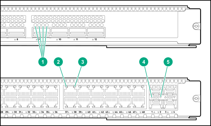
| 1* | Line module 4-channel port LEDs |
| 2 * | Line module port LED for upper port |
| 3* | Line module port LED for lower port |
| *4 | Line module port LED for upper uplink port |
| 5* | Line module port LED for lower uplink port |