Scenario 1

This example illustrates how an 8325 switch can be connected to a VMware NSX.
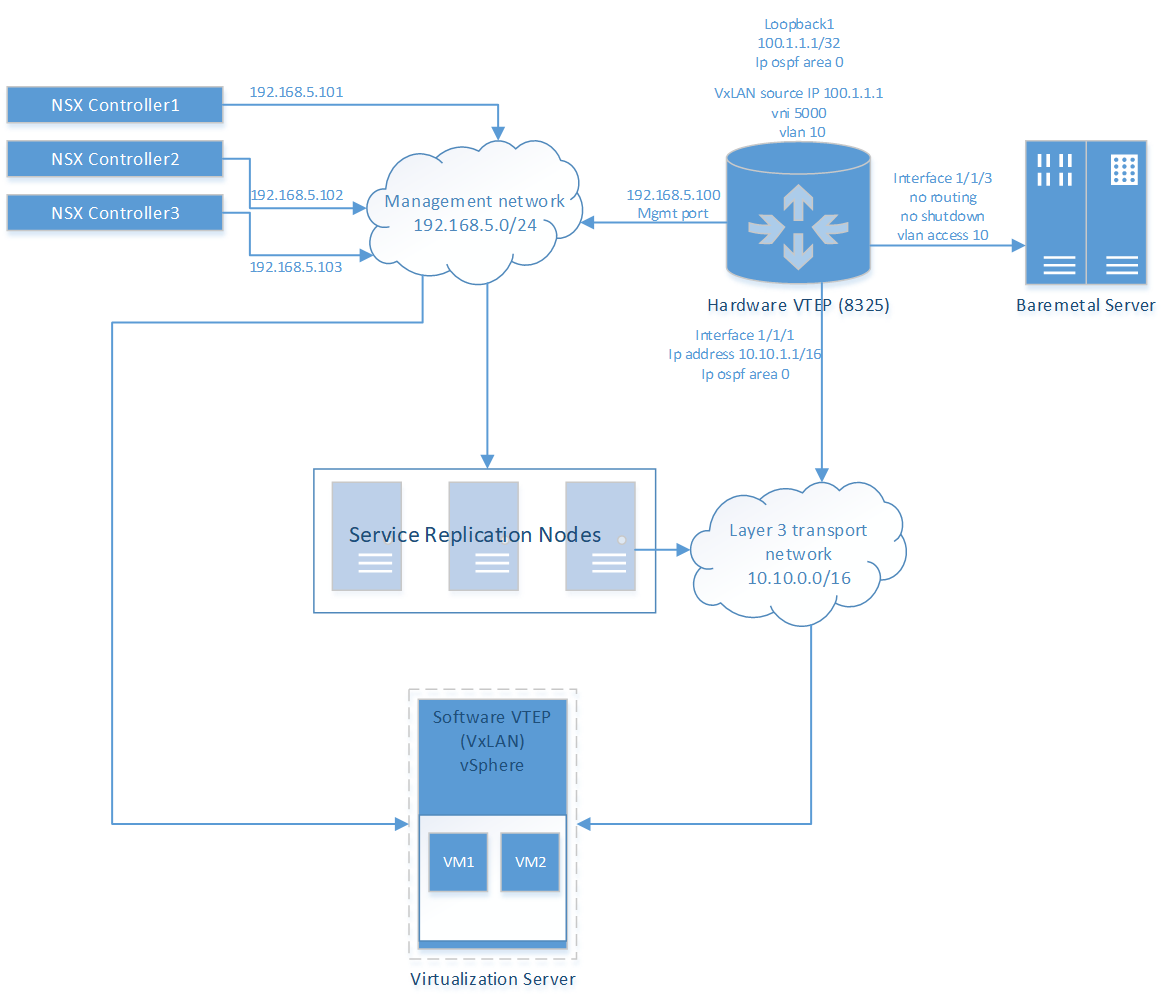
Key components

  • NSX controllers: Central control point for all logical switches in the network.

  • Management network: Network on which the 8325 switch communicates with the NSX controllers.

  • Hardware VTEP (8325 switch): Communication with the NSX controller occurs via the switch management port (which operates as a DHCP client by default). Interface 1/1/1 links the switch to the layer 3 network. Interface 1/1/3 extends the layer 2 domain over a VXLAN and links the switch to the bare metal server. OSPF is used to enable the routed layer 3 underlay network.

  • Bare metal server: Physical server providing network services.

  • Layer 3 transport network: The underlay network which provides routing functionality.

  • Virtualization server: The virtualization server is managed by VMWare VSphere. It hosts software VTEPs which perform VXLAN encapsulation for VMs deployed in virtual servers (such as an ESXi server).

Procedure
  1. On the 8325 switch:
    1. Enable interface 1/1/1, assign the IP address 100.1.1.1/24 to it, and configure OSPF.
      switch# config
      switch(config)# interface 1/1/1
      switch(config-if)# ip address 100.1.1.10/24
      switch(config-if)# ip ospf area 0
      switch(config-if)# no shutdown
      switch(config-if)# exit
      switch(config)# router ospf 1
      switch(config-ospf)# router-id 1.1.1.1
      switch(config-ospf)# router-id 1.1.1.1
      switch(config-ospf)# router-id 1.1.1.1
    2. Create VLAN 10.
      switch(config)# vlan 10
      switch(config-vlan-10)# exit
    3. Create a loopback interface 1 with IP address 100.1.1.1/32 and assign it to OSPF area 0 on the default VRF.
      switch(config)# router ospf 1 vrf default 
      switch(config-ospf-1)# exit
      switch(config)# interface loopback 1
      switch(config-loopback-if)# ip address 100.1.1.1/32
      switch(config-loopback-if)# ip ospf 1 area 0
      switch(config-loopback-if)# exit
      switch(config)# 
    4. Enable interface 1/1/3 and assign VLAN 10 to it.
      switch(config)# interface 1/1/3
      switch(config-if)# no shutdown
      switch(config-if)# no routing
      switch(config-if)# vlan access 10
      switch(config-if)# exit
    5. Create VXLAN interface 1 and assign the source IP address 100.1.1.1/24 to it.
      switch(config)# interface vxlan 1
      switch(config-vxlan-if)# source ip 100.1.1.1
      switch(config-vxlan-if)# no shutdown
    6. Create VNI 5000, and assign VLAN 10 to it.
      switch(config-vxlan-if)# vni 5000
      switch(config-vni)# vlan 10
      switch(config-vni)# exit
      switch(config-vxlan-if)# exit
    7. Configure the HSC manager address.
      switch(config)# hsc
      switch(config-hsc)# manager ip 10.10.10.1
    8. Enable the HSC. You are prompted to use the default certificate installed on the switch to secure the connection with the manager. Type y.
      switch(config-hsc)# enable
      Trust Anchor (TA) profile configurations are not used for HSC
      authentication. Instead HSC will store the CA certificate from the
      HSC controller during the first TLS handshake and use it for all
      future authentications with HSC servers. This CA certificate will
      not be used for any other certificate-based authentication. Do you
      want to continue (y/n)? y
    9. Make a copy of the default certificate (local-cert) in PEM format. You need to configure this certificate on the NSX manager.
      switch# show crypto pki certificate local-cert pem
        Certificate name: local-cert
        Associated Applications:
           captive-portal, hsc, https-server, syslog-client
        Certificate status: installed
        Certificate type: self-signed
          -----BEGIN CERTIFICATE-----
          MIDITCDskKkeLkDKfjlsafkdjLdfkejwlisfuslekfjsdkfjelfrjsekfslkefjselfkjslde8383
          ...
          3md0k4o9vjksdoijeknkviocvhsksdoeo399((jifiIIIHFKwlIelId8rekILF:IofJe,kei(gfo9
          -----END CERTIFICATE------
      Copy the lines between ----BEGIN CERTIFICATE----- and -----END CERTIFICATE-------.
  2. On the NSX manager, add the switch certificate using the vSPhere Web Client. Select Networking & Security and then Service Definitions. On the Hardware Devices tab, click Add (+) and paste the certificate into the appropriate box.
    switch# show crypto pki certificate local-cert pem
      Certificate name: local-cert
      Associated Applications:
         captive-portal, hsc, https-server, syslog-client
      Certificate status: installed
      Certificate type: self-signed
        -----BEGIN CERTIFICATE-----
        MIDITCDskKkeLkDKfjlsafkdjLdfkejwlisfuslekfjsdkfjelfrjsekfslkefjselfkjslde8383
        ...
        3md0k4o9vjksdoijeknkviocvhsksdoeo399((jifiIIIHFKwlIelId8rekILF:IofJe,kei(gfo9
        -----END CERTIFICATE------
    For more information on configuring the NSX manager, refer to the VMware NSX documentation.