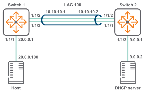
DHCP relay scenario 3 (IPv4)
In this scenario, host on switch 1 reaches the DHCP server on switch two via a LAG. The physical topology of the network looks like this:
Procedure
-
On switch 1:
- Create LAG
100 and assign an IP address to it.
switch# config switch(config)# interface lag 100 switch(config-lag-if)# ip address 10.0.10.1/24 switch(config-lag-if)# lacp mode active switch(config-lag-if)# exit switch(config)# - Assign an IP address to interface
1/1/1 and a an IP helper address to reach the DHCP server.
switch(config)# interface 1/1/1 switch(config-if)# ip address 20.0.0.1/8 switch(config-if)# ip helper-address 9.0.0.2 - Assign interfaces
1/1/2 and
1/1/3 to LAG
100
switch(config-if)# interface 1/1/2 switch(config-if)# lag 100 switch(config-if)# interface 1/1/3 switch(config-if)# lag 100 switch(config-if)# exit switch(config)# - Create a route between
10.0.10.2 and
9.0.0.0.
switch(config)# ip route 9.0.0.0/24 10.0.10.2
- Create LAG
100 and assign an IP address to it.
-
On switch 2:
- Create LAG
100 and assign an IP address to it.
switch# config switch(config)# interface lag 100 switch(config-lag-if)# ip address 10.0.10.2/24 switch(config-lag-if)# lacp mode active switch(config-lag-if)# exit switch(config)# - Assign interfaces
1/1/1 and
1/1/2 to LAG
100
switch(config-if)# interface 1/1/2 switch(config-if)# lag 100 switch(config-if)# interface 1/1/3 switch(config-if)# lag 100 switch(config-if)# exit switch(config)# - Assign an IP address to interface
1/1/3.
switch(config)# interface 1/1/3 switch(config-if)# ip address 9.0.0.1/24 - Create a route between
20.0.0.0 and
10.0.10.1.
switch(config)# ip route 20.0.0.0/8 10.0.10.1
- Create LAG
100 and assign an IP address to it.