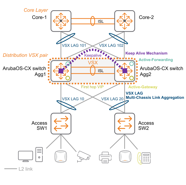
VSX solution topology overview
Active gateway support: Active gateways can be configured for active-active routing. VRRP can be used, as an alternative, for active-standby routing.
ISL links assigned to higher bandwidth: An ISL link has a higher bandwidth compared to VSX links. When planning the topology, consider sizing the ISL link according to the traffic volume required for the east-west traffic of a single-homed VSX during a failover scenario.
Reducing traffic loss: It is recommended, but not required, that each VSX LAG has at least two member links. The two links originate from two different line cards on each side of the VSX switches for a total of four member links per switch segment. This configuration reduces the possibility of traffic loss because of a line card reboot. The spanning of member links across line cards is applicable only to 8400 series switches.
Same VLAN configurations: Both VSX switches have the same VLAN configurations. Make sure that no topology loop is formed because an ISL is added as a member to all the VLANs by default. You can make configuration synchronization automatic between the VSX switches by enabling VSX synchronization.
Upstream device from VSX switches: Connections to the upstream device from the VSX switches have sufficient bandwidth to handle traffic from all VSXs.
Core-1 and Core-2, shown in the following figure, can be third-party devices, as long as they support LACP for downstream connectivity to the VSX LAG. VSX Synchronization syncs from the primary switch (Aggregate-1) to the secondary switch (Aggregate-2).
To configure Core-1 and Core-2 with ArubaOS-CX, see Configuring core 1 and core 2.
To configure the aggregate 1 and aggregate 2, see Configuring aggregate 1 and aggregate 2 switches.
To configure the access switch, see Configuring the access switch.