Network requirements
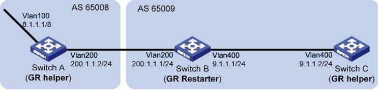
In the following figure, all switches are BGP switches. There is a eBGP connection between Switch A and Switch B. Switch B and Switch C are connected over an iBGP connection. Enable GR for BGP so that the communication between Switch A and Switch C is not affected when an active/ standby main board switchover occurs on Switch B.