Meshing routers and switches
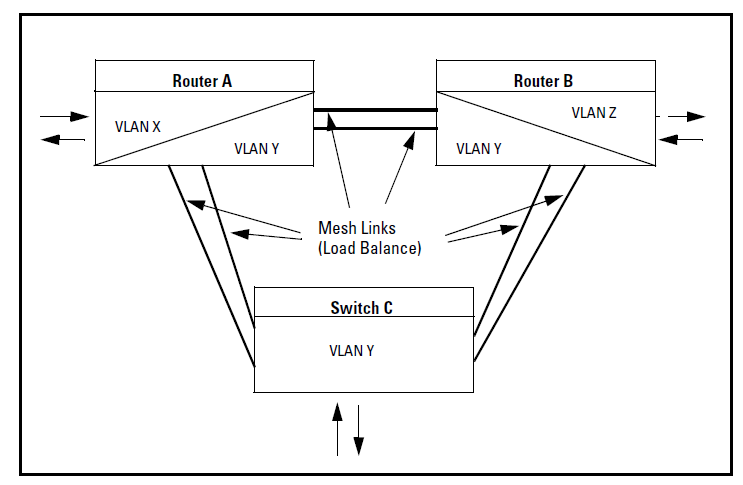
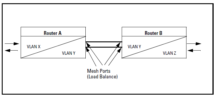
When Router A has no ports belonging to VLAN Z, the packets arriving on Router A’s non-mesh ports at VLAN X can be routed to VLAN Y, travel through the mesh, and arrive at Router B. After that they can be routed from VLAN Y to VLAN Z.
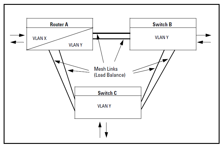
A router mesh
Switches and routers can be meshed together to create more complex local area networks with many redundant mesh links. Load balancing utilizes redundant links in the mesh to deliver traffic efficiently.
Packets arriving at Router A’s non-mesh port at VLAN X may be routed to VLAN Y, then switched through the mesh to a host connected to Switch B. Depending on the cost of the link between Router A and Switch B, the packets may be delivered to Switch C, and then forwarded to Switch B if that mesh path is less costly.
Packets arriving at the non-mesh ports for Switch B and Switch C may need to reach Router A. These packets are delivered through the mesh with the least mesh path cost.
Meshing with one router and two switches
The following example shows two routers and one switch that are meshed together. Packets arriving at the non-mesh ports on VLAN X on Router A may be routed to VLAN Y. Load balancing determines which port Router A should send the packets to in order for the packets to reach Router B.
Meshing with two routers and one switch